Quick Start
The device is shipped without any pre-installed sensor modules.
Sensor modules that require connection to the internal interfaces must be installed by opening the device enclosure. For example, sensor modules with a dedicated control pin, such as CO01, must be connected to the corresponding internal interface. Sensor modules that use an adapter can be connected directly to the external interfaces without opening the enclosure. Refer to the following diagram for the sensor interface layout and connection locations.
Sensor Interfaces
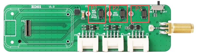
RD01 provides three internal sensor interfaces for connecting compatible sensor modules. The interfaces differ in their communication and control methods, as shown below.
| Sensor Interface | Communication | Control Pin | Compatible Devices |
|---|---|---|---|
| P1 | Sensor-specific | GPIO21 | CO01 |
| P2 | Sensor-specific | — | CH01, VO01, SV01 |
| P3 | I²C (SDA/SCL) | — | Buzzer |
The buzzer must be connected to Interface 3. This interface communicates with the connected device through the SDA and SCL lines.
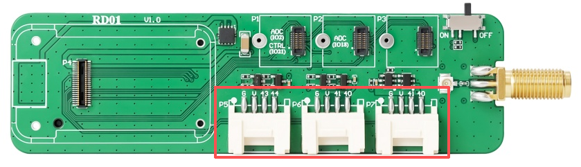
The three external sensor interfaces are all based on I²C. Refer to the corresponding schematic for the pin assignments.
| Interface | Connector | Pinout (Left to Right) |
|---|---|---|
| P5 | PH1.25-4P | GND, VCC, GPIO43, GPIO44 |
| P6 | PH1.25-4P | GND, VCC, GPIO41, GPIO40 |
| P7 | PH1.25-4P | GND, VCC, GPIO41, GPIO40 |
Sensor Example
For usage examples of the compatible sensor modules, refer to the RadioCore_Kit documentation.