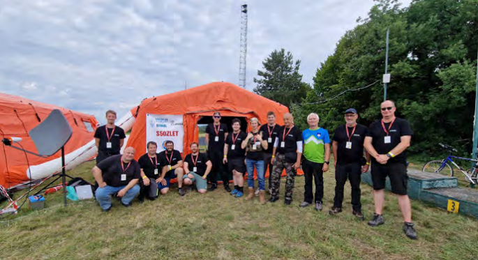
ZLET is the largest scouting gathering in Slovenia, bringing together scouts from across the country and offering a wide range of activities focused on nature, sports, creativity, and learning. The event takes place every four years, with each edition hosted in a different location throughout Slovenia.
In addition to supporting the event infrastructure, we assisted the scouts in deploying a wireless internet network across the campsite, enabling more efficient organization and communication throughout the various activities.
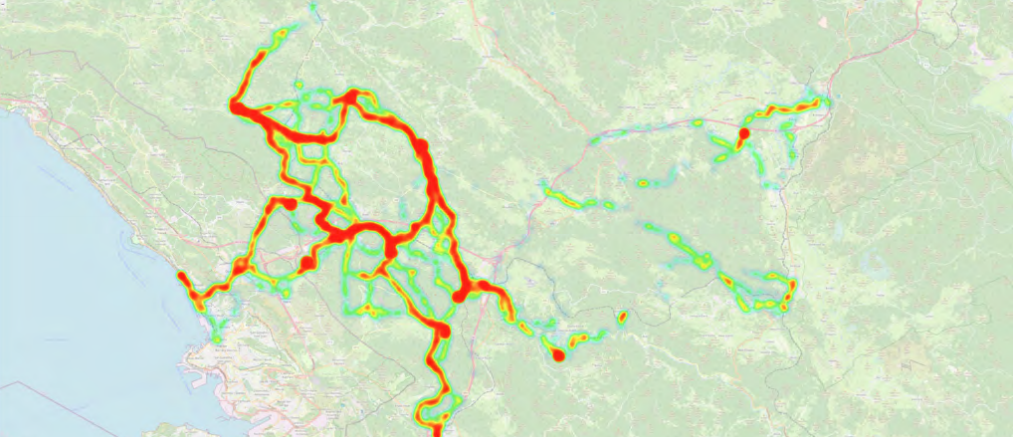
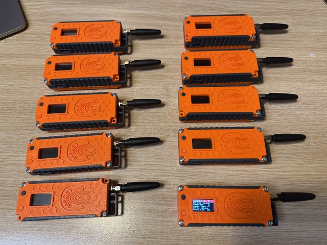
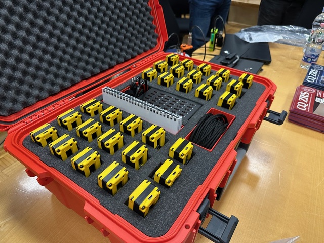
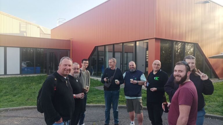
As part of the technical program, our amateur radio team prepared a series of activities focused on modern radio technologies. During the camping program, we conducted field testing of LoRa APRS tracking devices. For this occasion, we specially prepared the trackers for ZLET using Heltec Wireless Tracker modules and custom 3D-printed enclosures. We assembled 30 trackers, while an additional 10 units were provided by Radio Club Koper.
In total, 40 scout teams were equipped with trackers, allowing us to monitor their locations in real time. This provided participants with hands-on experience of radio-based position tracking in an environment without internet infrastructure, demonstrating the practical value of LoRa and amateur radio technologies in the field.
On Saturday, August 2, 2025, we organized two workshops: an introduction to amateur radio and a practical demonstration of Amateur Radio Direction Finding (ARDF), commonly known as “Fox Hunting.” The ARDF workshop was led by S57CT (Franci Žankar).
Participants were also introduced to satellite communications through amateur radio satellites and Slow Scan Television (SSTV). Every attendee had the opportunity to make their first amateur radio contact, gaining direct experience with radio communications and developing a deeper understanding of the technology through hands-on practice.
The workshops were scheduled across four sessions, each with approximately 20 registered children. Due to adverse weather conditions, one session had to be canceled. Despite this, around 120 scouts participated in the activities overall.
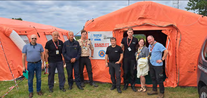
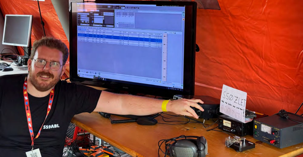
Throughout the event, we operated under the special callsign S50ZLET and established numerous HF radio contacts, further promoting amateur radio to participants and visitors alike.
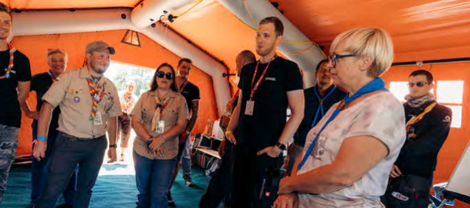
We also had the opportunity to present our work to several distinguished guests, including Dr. Nataša Pirc Musar, President of the Republic of Slovenia; Borut Sajović, Minister of Defence; Members of Parliament Lucija Tacer and Andreja Živic; Sandi Curk, Civil Protection Commander for the Notranjska Region; Aleš Klemenc, Head of the Notranjska Civil Protection Office; Andrej Sila, Mayor of Sežana; and Vanja Jelen, Deputy Mayor of Sežana.
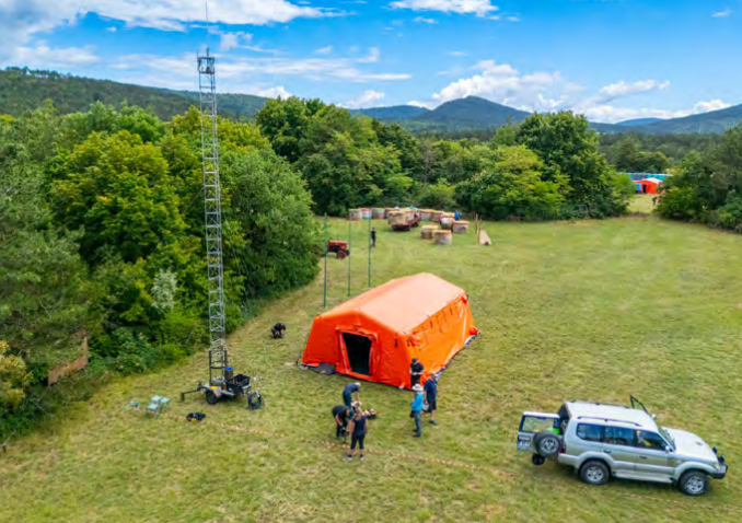
During these presentations, we highlighted our key activities, emphasized the importance of self-sufficient communications, and demonstrated how amateur radio systems can remain operational with only a reliable power source. Using EcoFlow batteries and solar panels, we showcased our ability to operate independently, including in emergency and off-grid situations.
Participation in ZLET 2025 made a significant contribution to promoting amateur radio among young people and the broader public. The event also reinforced the role of amateur radio operators as a technically skilled, community-oriented, and socially valuable group while demonstrating how technologies such as the Heltec Wireless Tracker can support education, outdoor activities, and resilient communications in real-world environments.
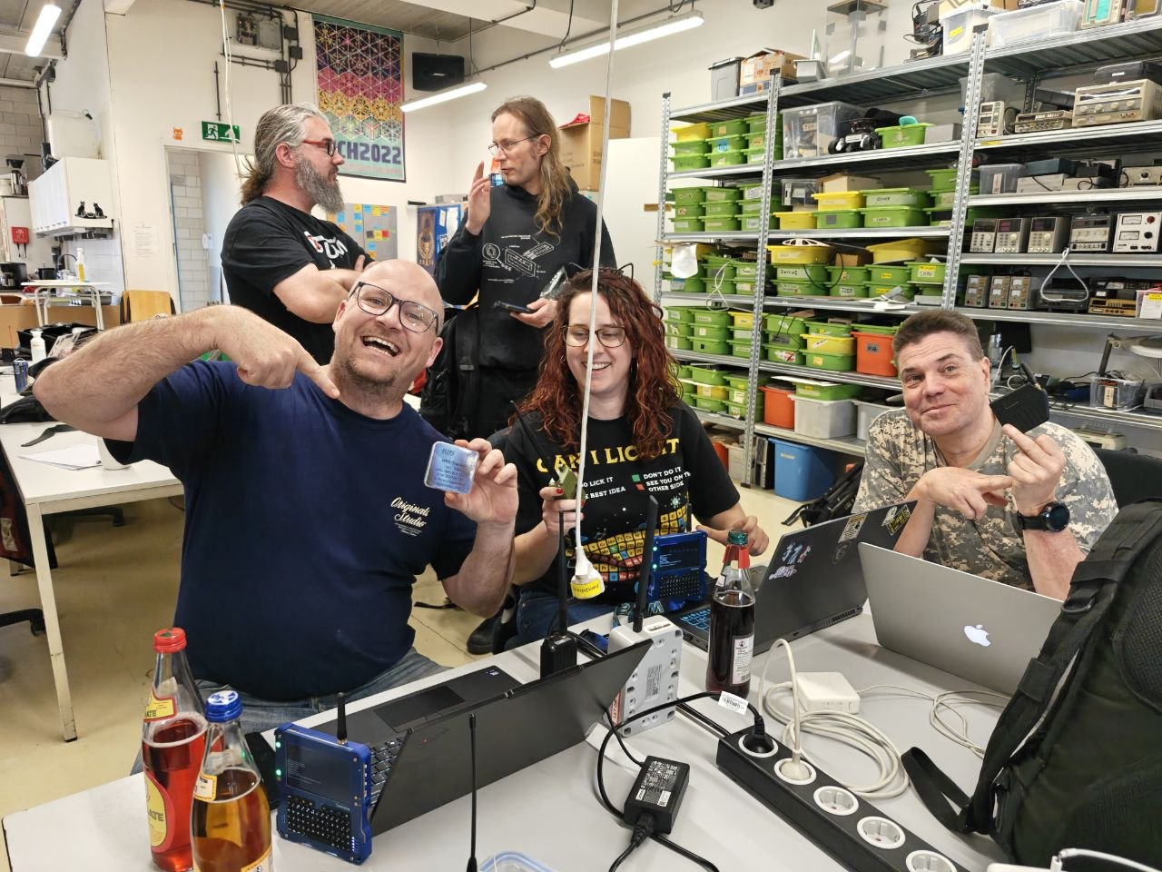
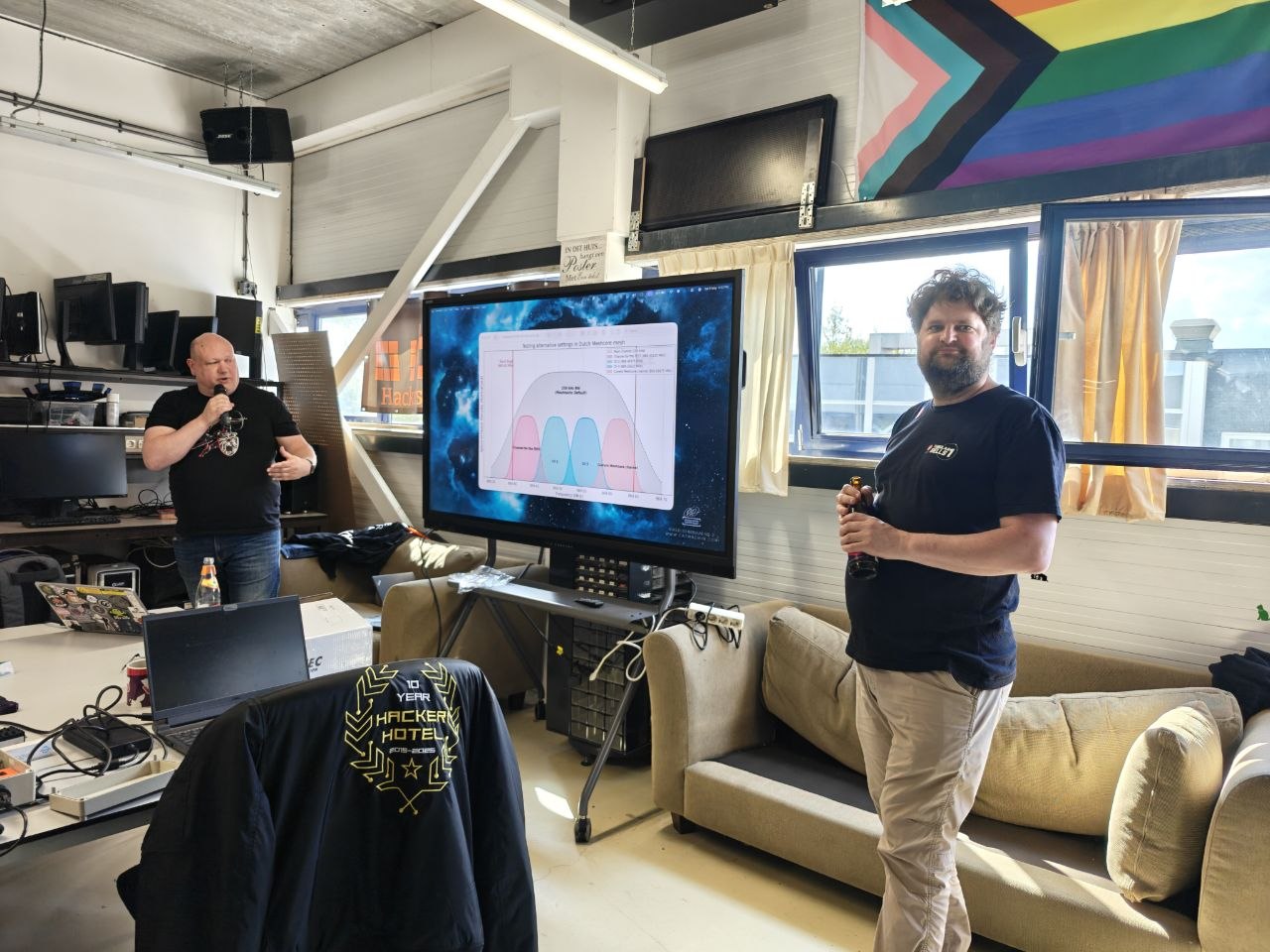
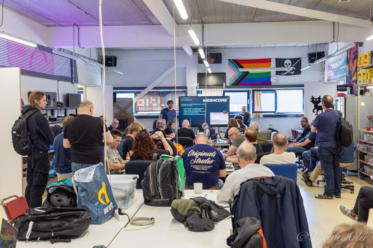
Heltec Automation recently supported a MeshCore community meetup held at Bitlair Hackerspace in the Netherlands, where local radio, LoRa, and mesh-networking enthusiasts gathered to exchange knowledge, test hardware, and discuss the future of decentralized communication networks.
The meetup was organized by members of the Dutch MeshCore community and attracted strong interest from local users. Before the event, organizers reported more than 50 expected participants, reflecting the fast growth of MeshCore activity in the Netherlands and the role of hackerspaces in accelerating real-world adoption. During the event, participants discussed a wide range of MeshCore and LoRa-related topics, including MeshCore basics, Companion flashing, radio fundamentals, LoRa transmission, channels, room servers, OTA router updates, local RF regulations, sensors over LoRa, network scalability, and practical outdoor deployments.
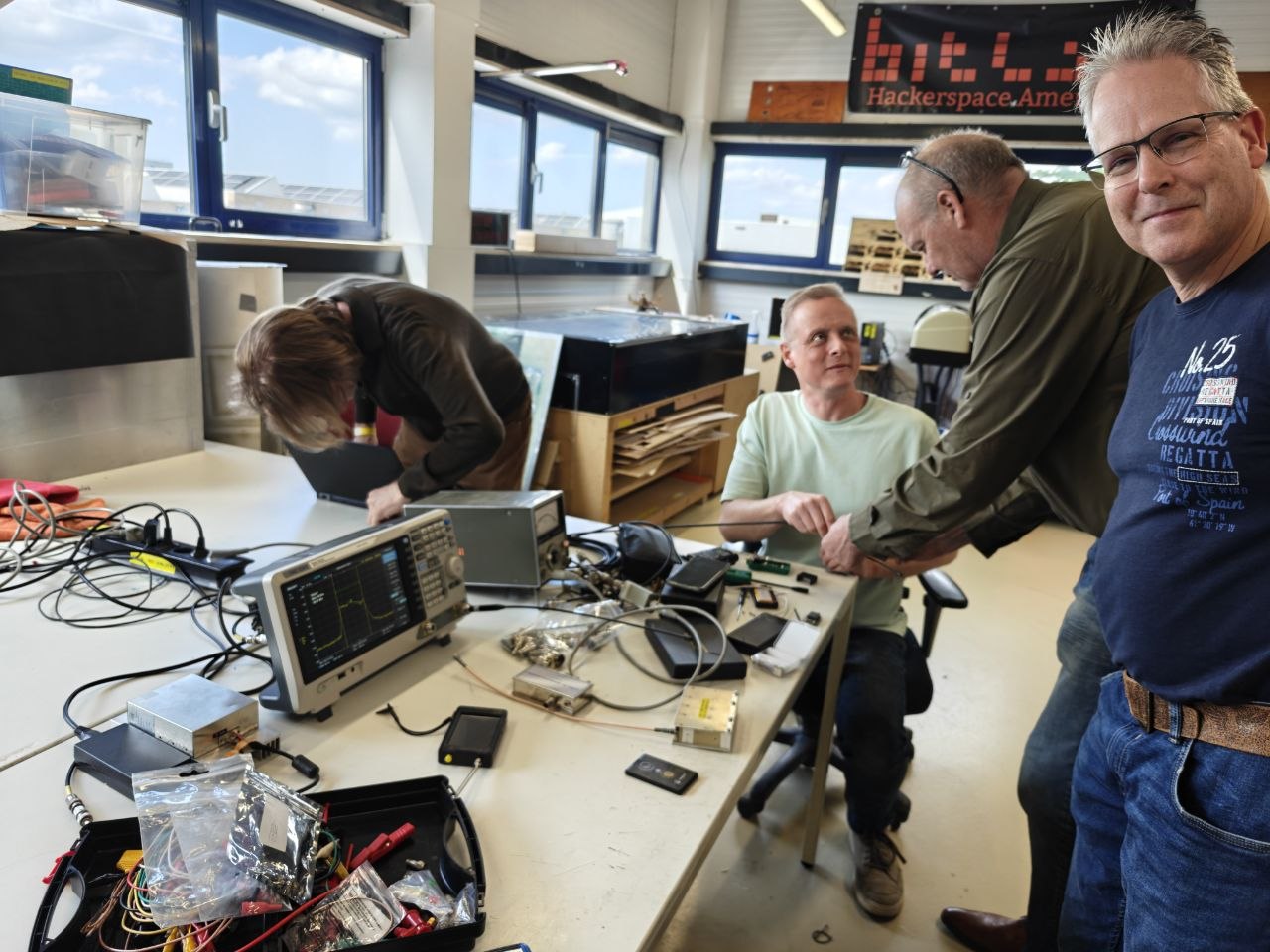
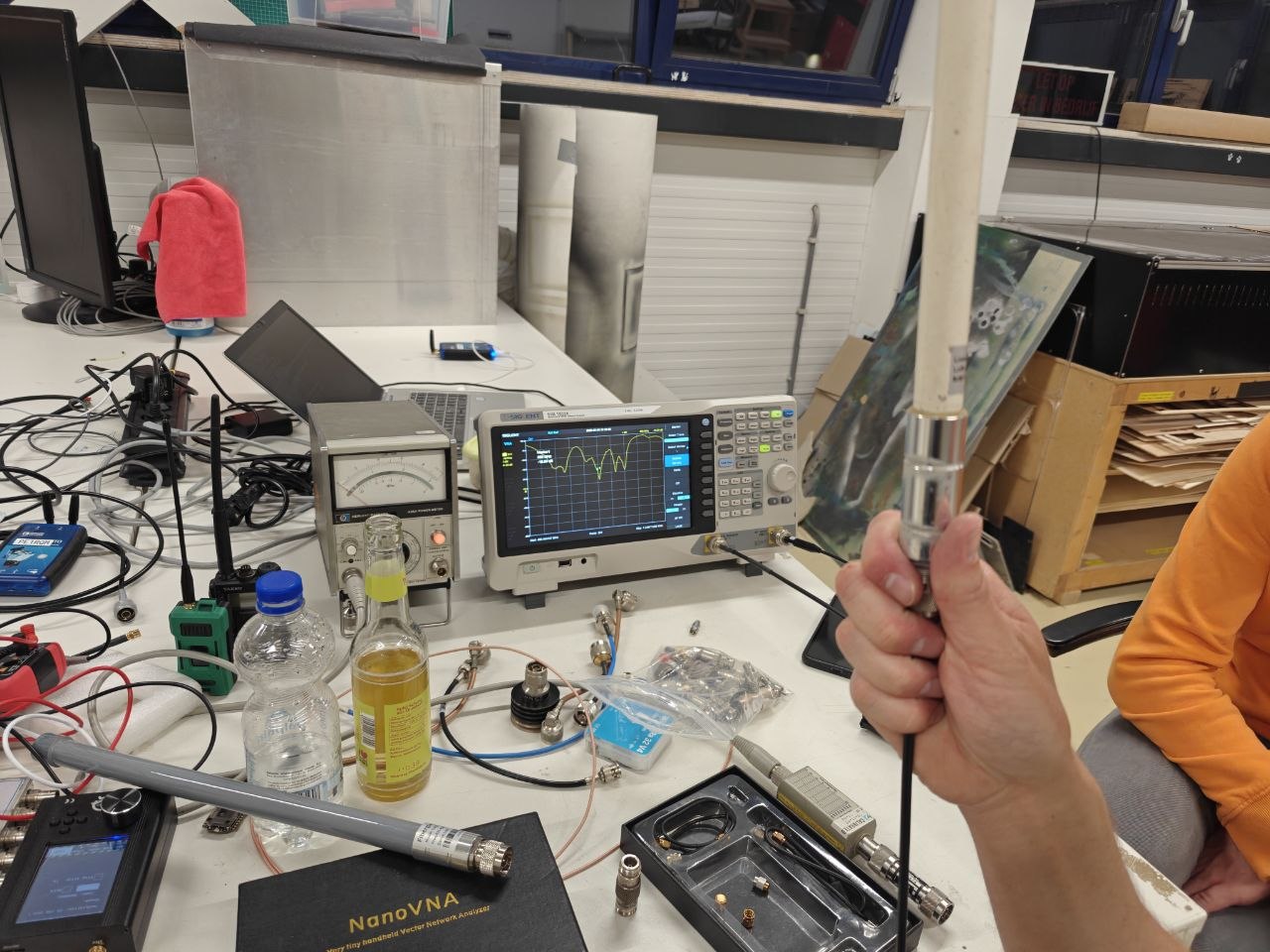
A key focus of the meetup was hands-on testing and technical validation. Community members brought professional RF test equipment, including VNAs, a spectrum analyzer with a rubidium reference, precision power meters, and SDR radios. These tools were used to evaluate antenna resonance, LoRa frequency accuracy, output power, and filter performance.
Heltec supported the meetup by providing hardware for demonstration and community testing. Around 30 kits based on Heltec V3 and V4 hardware were also prepared by community members for participants who needed additional devices for experimentation and deployment. Heltec also provided a dedicated discount code for meetup attendees to support further community adoption.
The event also coincided with the Dutch community’s move toward SF7 / CR5 configuration, giving participants an opportunity to configure devices together and discuss performance in a real local mesh environment.
For Heltec, the meetup provided valuable first-hand feedback from experienced users. In addition to positive community engagement, participants shared technical observations from RF and antenna testing. Heltec has forwarded this feedback to its internal engineering team for further review and will continue to use real-world community data to improve hardware documentation, accessories, and future product design.
“Real community deployments are extremely important to us,” said Heltec Automation. “Events like this help us understand how users actually build, configure, test, and improve mesh networks in the field. We are grateful to the Dutch MeshCore community for their openness, technical depth, and willingness to share practical feedback.”
The Netherlands has become one of the active regions for MeshCore experimentation, with new repeaters and community-led deployments continuing to appear. According to the organizers, future meetups are expected to continue every few months, helping keep the local mesh community active and connected.
Heltec will continue supporting community-led events, workshops, and real-world testing efforts around LoRa, MeshCore, Meshtastic, and decentralized IoT communication.
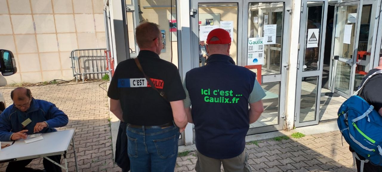
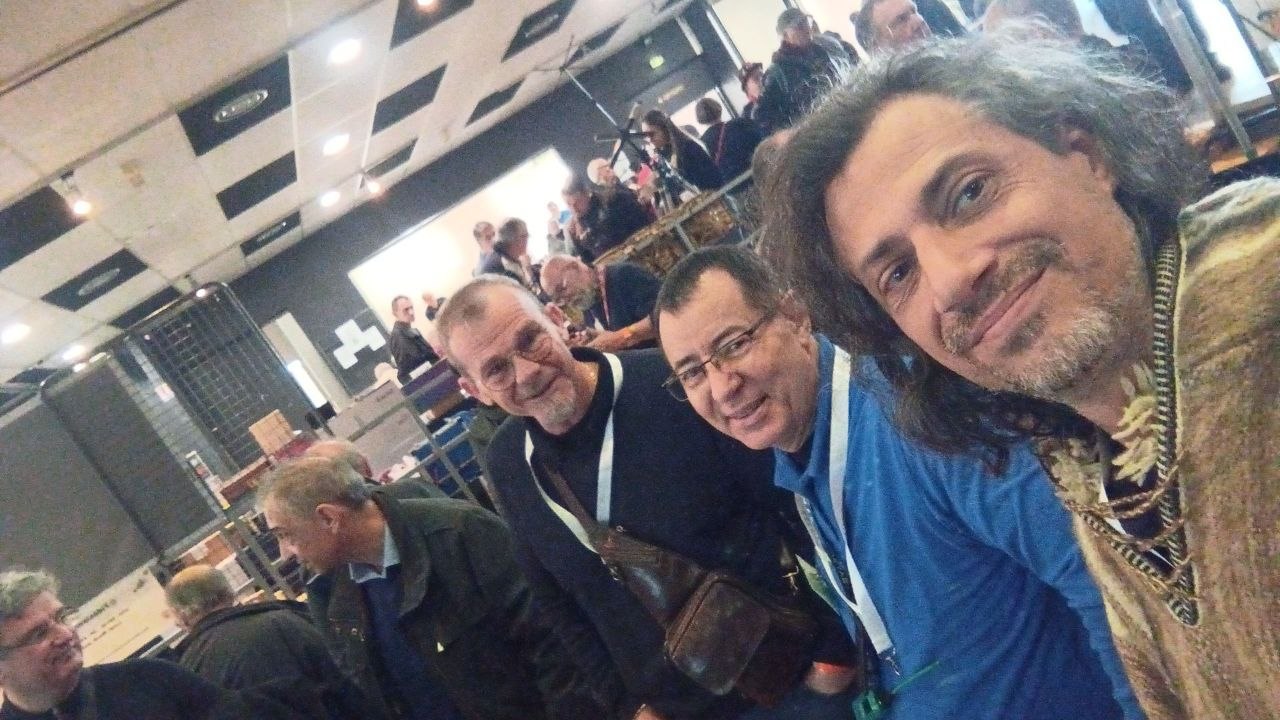
Before Ond’Expo 2026 officially opened its doors to the public, the venue was already abuzz with intense yet orderly preparations. The team from the Lyon Radio Club (F8KLY) warmly welcomed all participants, while volunteers swiftly dove into their respective tasks to finalize the setup of the exhibition booths.
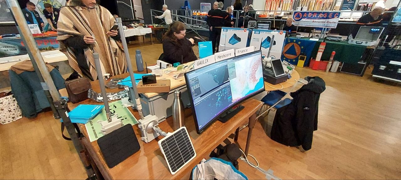
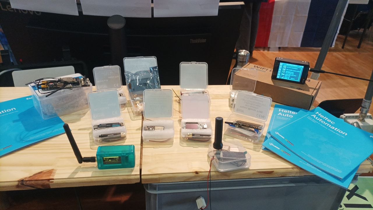
The Gaulix team’s booth was quickly brought to readiness. Equipment was progressively installed, and a network map was displayed on a screen, making the structure of the MeshCore network instantly clear. As team members continued to arrive, the pace on the floor gradually quickened, with everything falling into place for the imminent opening.
Once the exhibition opened its doors, a steady stream of visitors poured in. Veterans familiar with the Meshtastic ecosystem, newcomers eager to explore, and curious onlookers interested in LoRa communication constantly gathered in front of the booth. Questions, discussions, and demonstrations intertwined, keeping the entire booth in a state of high-energy activity throughout the day. Some visitors came seeking technical assistance; others wished to understand the differences between various devices and firmware; and some, encountering mesh networking for the very first time, sought to grasp the potential of this decentralized mode of communication.
Throughout the day, the Gaulix team provided continuous technical support and demonstrations: node flashing, parameter configuration, network debugging, and device installation. Every question was treated with seriousness, and every interaction became an opportunity to share knowledge. Amidst a relaxed and open atmosphere, technology ceased to be merely a tool; instead, it became a bridge connecting people.
Meanwhile, MeshCore technology emerged as one of the focal points of the event. Through intuitive demonstrations and explanations, the team showcased the practical application possibilities of this technology to the audience; its potential for rapid development also sparked widespread interest. After experiencing it firsthand, many visitors began to consider how they might introduce mesh networking into their own communities or projects.
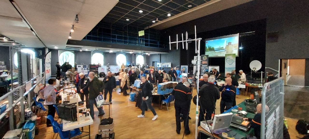
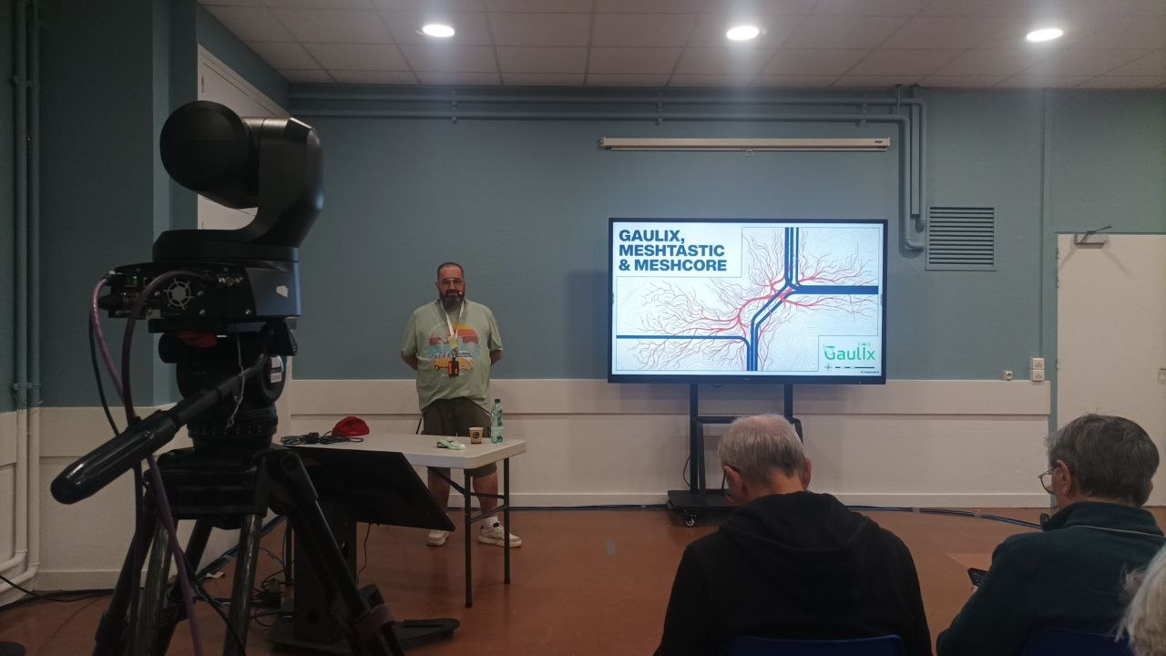
The exhibition was also punctuated by several memorable moments—from lighthearted and humorous interactions to high-quality technical presentations, and even an on-site prize raffle—ensuring the entire event maintained an excellent pace and a strong sense of engagement. In particular, when the technical lectures were simultaneously broadcast via online platforms, the event's influence extended far beyond the physical confines of the exhibition hall.
As the exhibition drew to a close, the pace gradually slowed, yet the exchange of ideas continued unabated. Outside the exhibition hall, some team members continued their discussions—ranging from the day’s demonstrations to future project concepts, and from antenna design to network deployment—with every topic flowing naturally into the next. This exchange, extending well beyond the confines of the trade show, perhaps represents the truest embodiment of the community spirit.
Ond’Expo 2026 ultimately drew to a close amidst an atmosphere that was both fast-paced and immensely fulfilling. It was not merely a showcase of technology, but a practical exercise in connection, collaboration, and sharing. Through this event, Gaulix once again demonstrated that the true value of a Mesh network lies not solely in the act of communication itself, but—more importantly—in the power of the community it inspires.
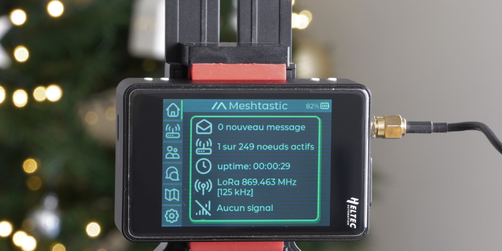
What can the Heltec Wireless Tracker v2 be used for ? In situations of disruption (unavailable cellular network, infrastructure overload, loss of coordination), the main problem is not just communication, but knowing the whereabouts of family members, friends, or clans. A LoRa/Meshtastic tracker provides a simple solution to this need: it allows for a basic awareness of location, without relying on a mobile network operator .
In practical terms, it becomes a distributed coordination tool . A group can track the movements of its members, visualize relative positions (azimuth), identify delays, deviations from the trajectory, or when a regrouping point has been reached . Whereas voice radio requires being available at the right time and manually plotting the position on a paper map, the tracker sends very precise and regularly updated information to the local Meshtastic network on your private channel.
It also makes perfect sense in a context of retreat and mobility. During a move to a safe location, or within a multi-site strategy (plans A, B, C), it allows confirmation that an individual or team has indeed reached a given area, without the need for lengthy or energy-intensive exchanges. This is particularly relevant if communications must remain brief, discreet, or infrequent .
Discreet use: A tracker can be configured to transmit periodically without human intervention. In case of a problem (incident, loss of contact, immobilization), the last known position becomes usable information. It's not a miracle solution, but it's often the only data available when everything else has failed.
Finally, in a mesh network like Meshtastic, the tracker doesn't work alone. It relies on a lightweight infrastructure of fixed or mobile nodes to relay information. This enables the creation of a collaborative location capability that is inherently resilient because it is distributed and without a central point.
Ultimately, the value of a tracker in a resilience strategy is not technological. It is operational: reducing uncertainty about people's locations and maintaining a minimum level of coordination when traditional methods fail.
When Heltec Automation offered me the opportunity to test their new tracker in advance, I saw it as the perfect opportunity to move beyond simple “classic node” use and explore a much more specific role: that of a field tracker .
Testing a product before its release is always interesting. But here, the idea was mainly to go beyond the technical specifications: to understand how this type of node performs in real-world conditions, what it actually brings to the field… and above all, where its limitations lie.
So I accepted without much hesitation, with one question in mind: can this add value to our resilient preparations?
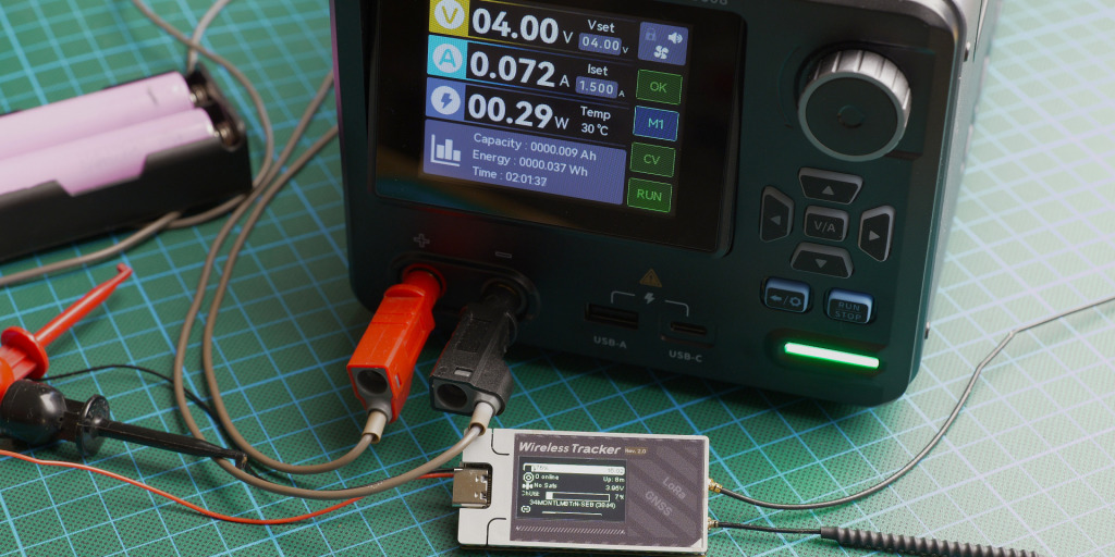
Measurement from scratch: 50 mA in standby/idle, 70 mA in current consumption and 850 to 950 mA at TX/Burst transmission.
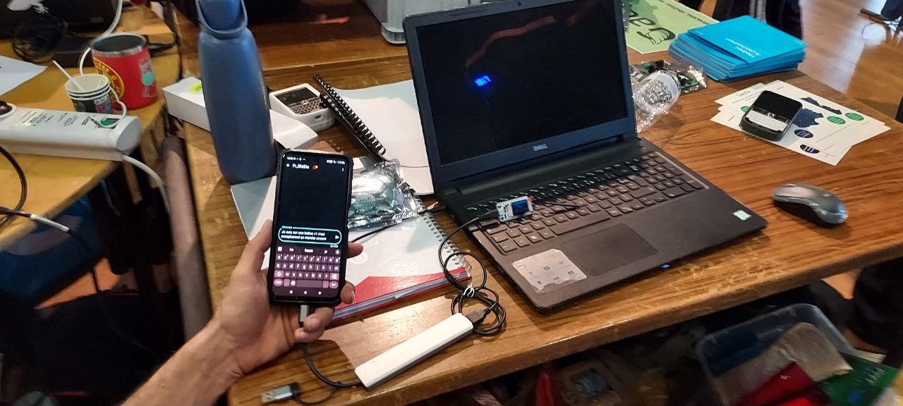
A. Operational context of the test with the Meshtastic Client role:
Power supply: 2 × 18650 2600 mAh batteries in parallel. Bluetooth: enabled. permanent exhibition at my local MQTT gateway ( Gaulix Canal Fr_Blabla ). approximately ten BLE connections during the test period (12 hours). approximately twenty LoRa TX messages were sent during the test period (12 hours).
note
The average consumption of the Client node over the period is 58 mAh
B. Operational context of the test with the Meshtastic Tracker role:
Power supply: 2 × 18650 2600 mAh batteries in parallel Bluetooth: enabled permanent exhibition at my local MQTT gateway ( Gaulix Canal Fr_Blabla ) approximately ten BLE connections during the test period (12 hours) approximately five LoRa TX messages during the test period (12 hours)
note
The average power consumption of the tracker node over the period is 37 mAh
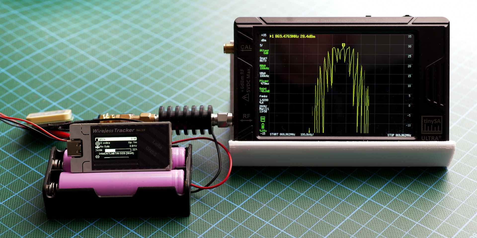
To measure the actual power output of the Heltec Wireless Tracker v2 (nRF52840) , I used a TinySA Ultra Plus spectrum analyzer with a 40 dB / 10 Wmax attenuator placed between the transmitter and the device to protect it from an excessively strong signal. The screenshot below shows a measured power of 28.4 dBm , with an accuracy of ±2 dBm. Considering the attenuator's actual calibration and the analyzer's margin of error, this measurement confirms that the advertised power level has been achieved .
Legislative reminders – Application to Meshtastic in the 869.4–869.65 MHz band
The region setting in Meshtastic is primarily used to adjust the frequency and duty cycle rules...
500 mW PAR = 27 dBm WORSE EIRP
This means that:
If your antenna has a gain of 2 dBi
And that your cable loses 0.5 dB
→ Your output power module should be set to around 25.5 dBm
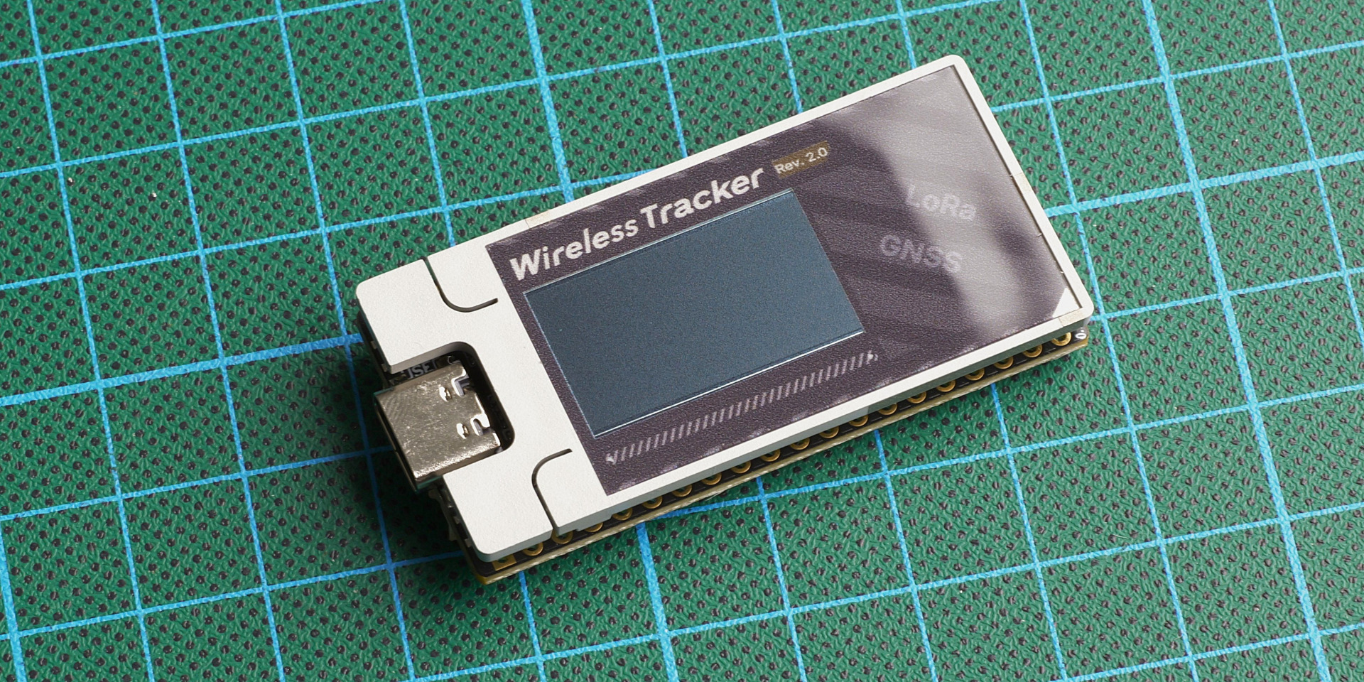
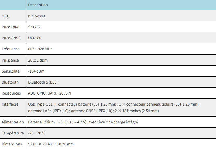
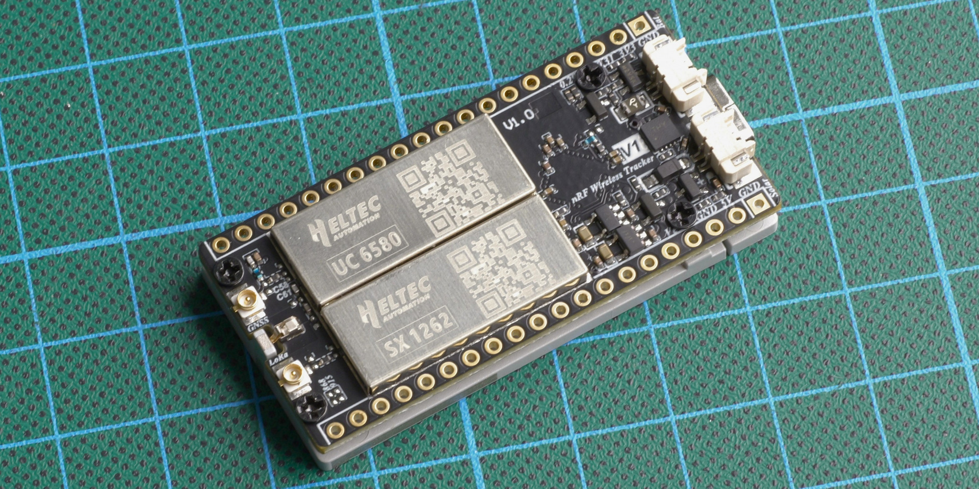
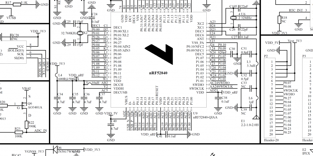
Following the mid-March launch of the ESP32-S3 version of the Wireless Tracker V2 , the next version will adopt an nRF52840 microcontroller, chosen to reduce power consumption while maintaining the same basic hardware architecture. LoRa communication relies on the SX1262 chip, accompanied by a KCT8103L amplifier front-end (PA/LNA) that stabilizes the signal and optimizes transmission and reception.
The UC6580 GNSS/GPS module provides positioning by utilizing multiple satellite constellations ( GPS, GLONASS, BeiDou, Galileo ), reducing positioning times and improving reliability in urban or wooded areas. Its optimized power consumption and intelligent sleep mode perfectly align with the nRF52840's design philosophy, ensuring that geolocation does not significantly impact the device's overall battery life.
Power management is handled by the CN3165 controller , which oversees the charging and powering of the battery and other components. The whole system forms a relatively coherent platform: a less power-hungry nRF52840 MCU, operational LoRa radio, active geolocation, and controlled battery life, all while remaining simple and robust in terms of hardware. However, the integration of this controller into the architecture is inherently limited to the use of a low-power solar panel (approximately 3 watts).
note
Note that even though the system can benefit from more advanced energy management by delegating control to an additional module ( such as an MPPT ), it's important to remember that this node is primarily designed for integrated tracking, for example in vehicles, where it will be highly autonomous. In standalone, autonomous use, its operation will remain dependent on the initial capacity of its battery.
🌿CN3165
A significant limitation of integrating the CN3165 into this type of node is the lack of intelligent power management. The circuit offers neither true load sharing (distribution between external power supply and battery) nor power path management. In practical terms, even with solar power available, the system relies directly on the battery to operate. Furthermore, unlike a more advanced BMS incorporating Schmitt trigger logic (for example, shutting down at 3.0V and restarting only at 3.5V), the CN3165's behavior is based on a single implicit threshold. As a result, the system can become stuck in an unstable state, unable to restart properly when the battery recharges slowly, particularly in degraded solar conditions.
🌿KCT8103L
Heltec Automation's choice to switch to the KCT8103L chip is simply explained by a better compromise between useful radio performance and power consumption.
In terms of performance, the gain doesn't come from higher transmission power, but from cleaner reception. The KCT8103L introduces less noise and improves sensitivity, which increases the truly usable signal-to-noise ratio (SNR). In LoRa, this parameter determines the effective range and stability of the transmission. In practical terms, a node picks up weak signals better and decodes more reliably, which has a much greater impact than a few extra dBm in transmission power.
In terms of power consumption, the difference is clear. Power-oriented solutions like the GC1109 draw high currents during transmission, resulting in lower overall efficiency. The more balanced KCT8103L reduces power consumption while maintaining superior performance on the actual link. The result is a better range-to-energy ratio, essential for autonomous nodes, and the risk of low battery charge during transmission no longer triggers a node reboot.
In summary, Heltec has abandoned a "transmit louder" logic for a better transmission logic, simultaneously improving link quality and energy efficiency.
At the end of this test, it's important to place this node in its true category: it's not a "turnkey" product, ready to use right out of the box, but rather a maker- oriented platform . The Heltec Wireless Tracker V2 (nRF) requires understanding, adaptation, and integration. It's clearly aimed at those willing to get their hands dirty with configuration, power supply, and sometimes even hardware optimization.
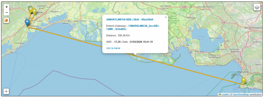
It is precisely in this context that it becomes interesting. For behind this unfinished approach lies real technical potential. The radio performance is particularly attractive, with a transmission power of up to 28 dBm , combined with the sensitivity provided by the KCT8103L RF front-end . In the field, this is clearly demonstrated: during my tests with an 8dBi antenna , an uplink was established over 130 km with a signal-to-noise ratio (SNR) of -17.25 , which remains perfectly usable in LoRa. This type of result clearly illustrates the node's ability to maintain long-distance communications under real-world conditions and clearly places it above many other nodes in terms of raw radio performance.
However, this node requires some choices. Powering it, especially with solar power, quickly reveals its limitations if a "plug and play" approach is used. The lack of advanced energy management necessitates a holistic approach to its integration, taking into account the specific usage context.
It is precisely from this perspective that I see the value of this tracker. Rather than considering it as a universal standalone device, I see it as a component to be integrated into a larger system . For my part, it will naturally find its place in my van, with a fixed power supply, where I can control the available energy and fully utilize its radio capabilities.
In this type of integration, its limitations become secondary, and its strengths take precedence: compactness, energy efficiency, and above all, radio performance. Ultimately, this node is a highly technical niche product, but a tool that reveals its full potential when used in an environment designed for it.
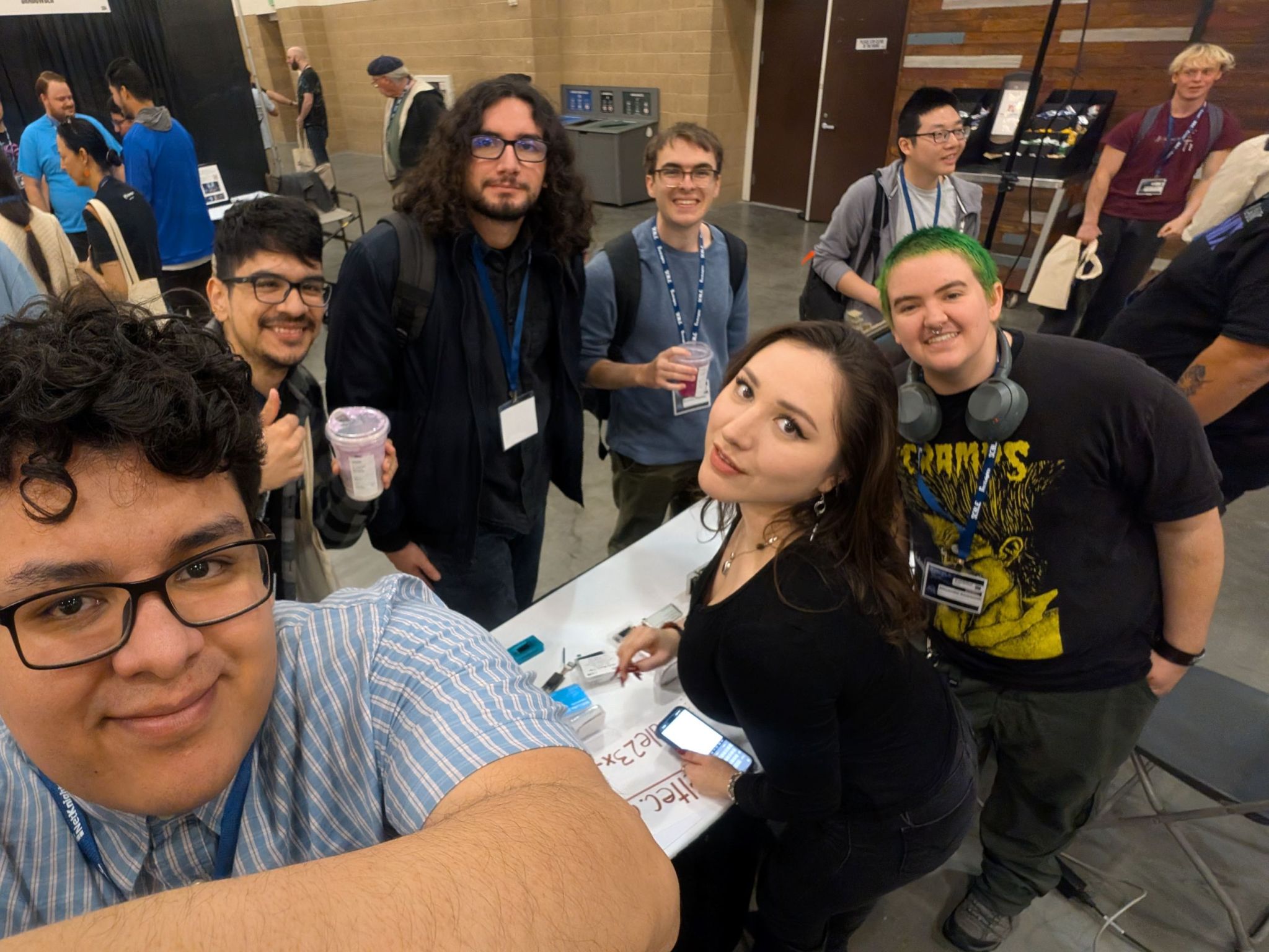
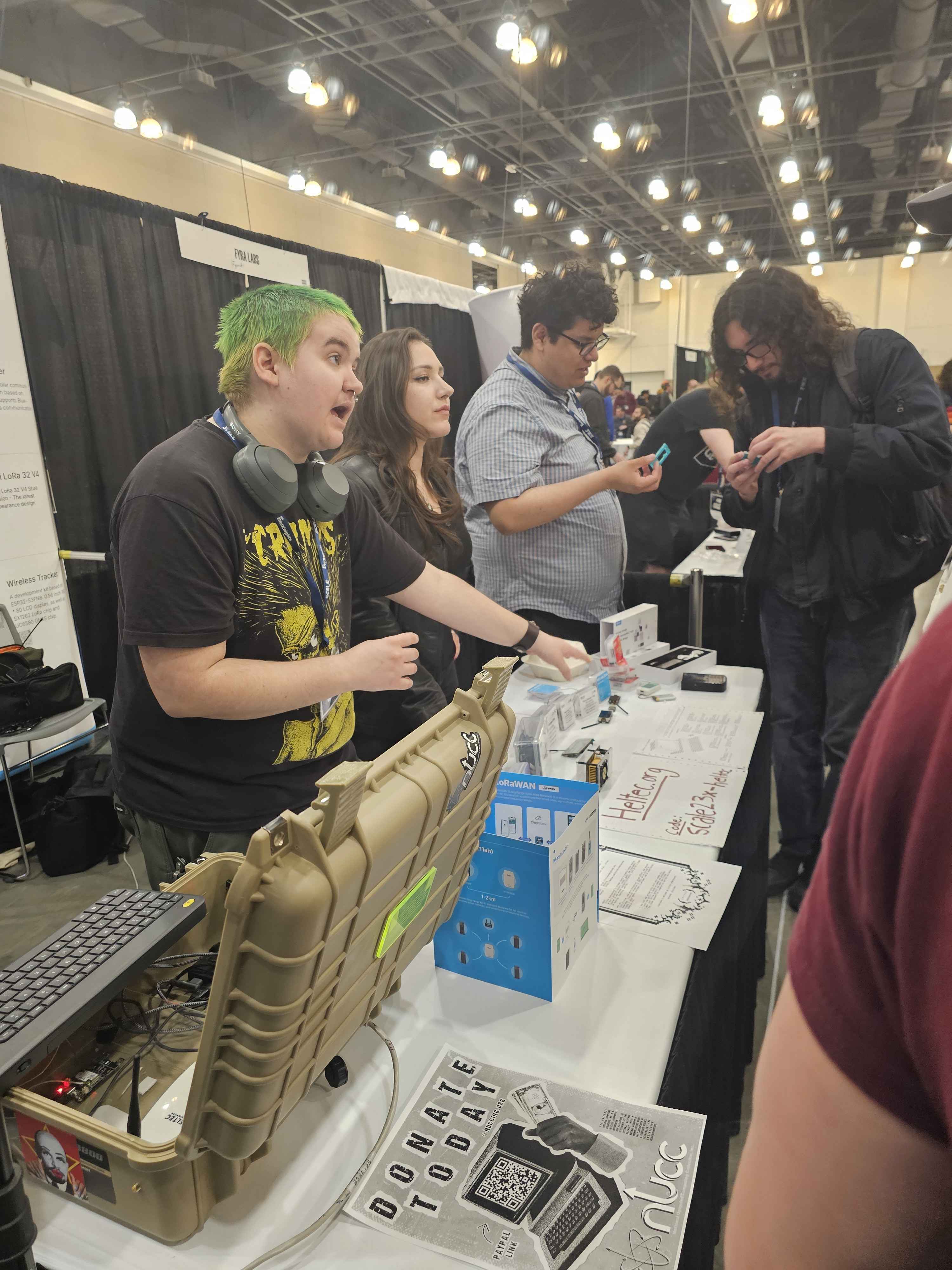
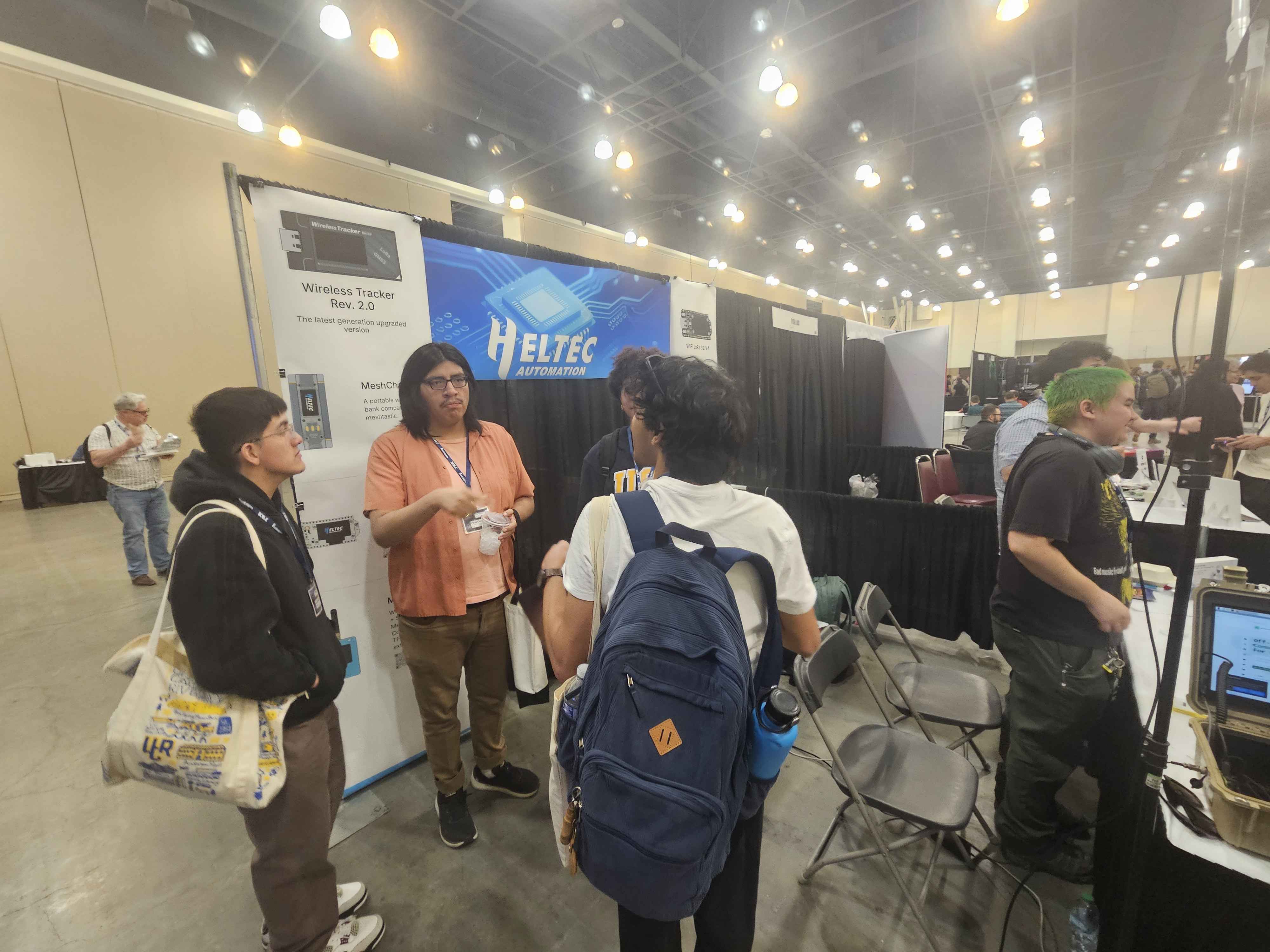
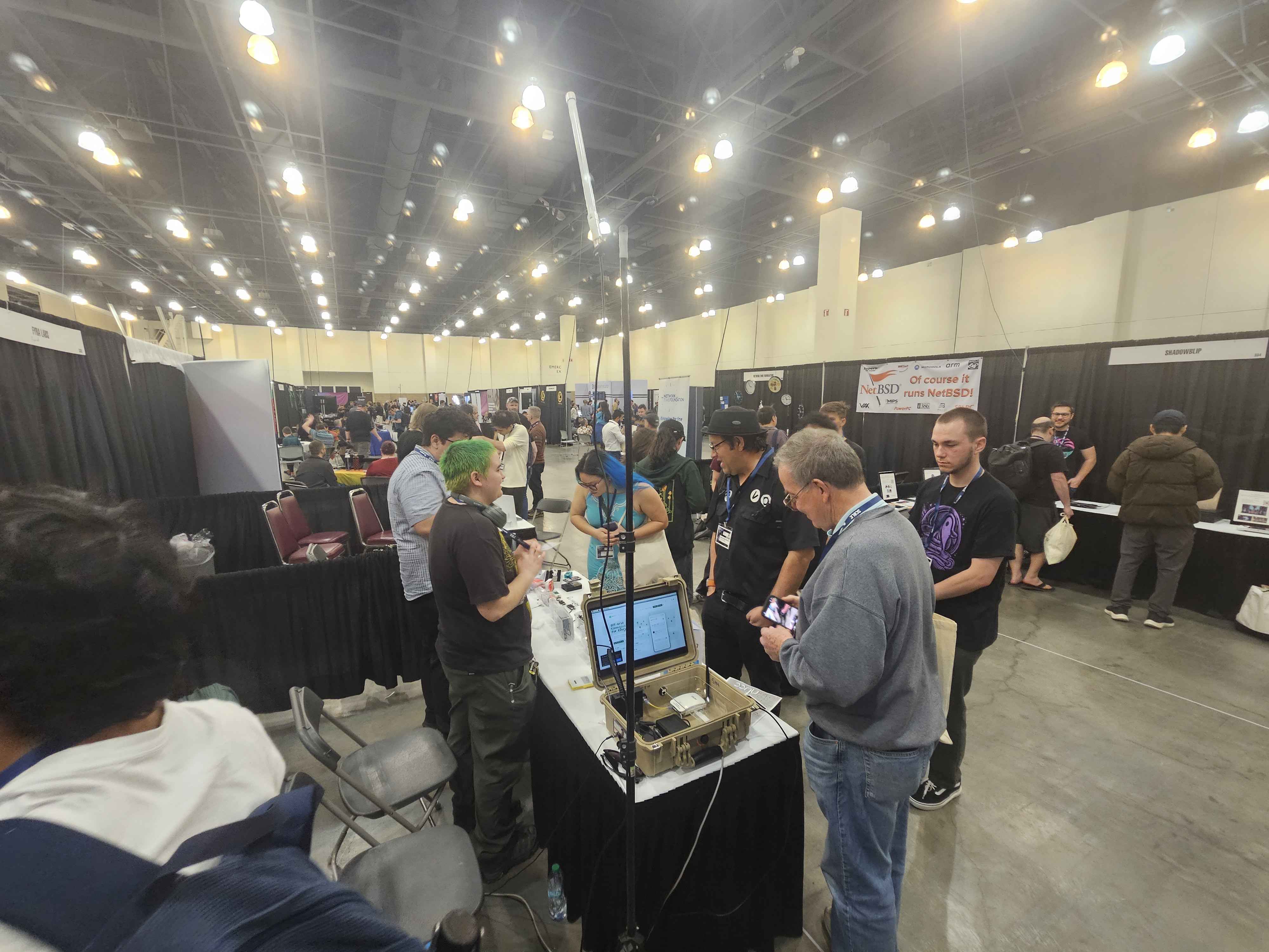
PASADENA, Calif., March 17, 2026 /PRNewswire/ -- Heltec, a global leading enterprise specializing in IoT and smart hardware, today announced the successful conclusion of its participation in the Southern California Linux Expo (SCALE), held in Pasadena, California, USA. With comprehensive on-site volunteer support from top university cybersecurity societies and professional industry organizations, Heltec showcased its complete matrix of core products at the event, delivering strong results in expanding brand influence, engaging with clients and industry peers, and building its technical reputation within the North American market. The company’s booth emerged as one of the most popular and highly visited attractions throughout the expo.
As a pivotal industry exchange platform in North America, SCALE centers on embedded technologies, IoT applications, and cybersecurity. The annual event brings together global industry vendors, technical experts, enterprise clients, and university research communities, serving as a core channel for technology implementation, business matchmaking, and cross-sector industry collaboration. During the expo, Heltec leveraged its dedicated booth to present a comprehensive display of its full portfolio, including embedded development hardware, LoRa communication modules, and IoT terminal devices, alongside tailored vertical industry solutions for industrial IoT, smart hardware development, and device security protection. The showcase fully demonstrated the company’s core competitive strengths in IoT hardware R&D, low-power communication technologies, and device security adaptation.
Notably, Heltec received professional volunteer on-site technical support from the Offensive Security Society (OSS), a student-led organization based at California State University, Fullerton (CSUF). As a student-run group focused on practical cybersecurity offensive and defensive techniques, technical knowledge sharing, and tech talent development, OSS follows a long-standing philosophy of hands-on technical learning. We actively promote cybersecurity culture across academic and industry circles through a wide range of initiatives, including educational workshops, industry competitions, and bug bounty programs.
Additional hands-on volunteer technical support was provided by Cyber@UCR, the official cybersecurity technical team affiliated with the University of California, Riverside (UCR). Committed to advancing knowledge sharing and technical research in the computer security field through hands-on competitive events and laboratory experimentation, the Cyber@UCR team delivered expert volunteer assistance for Heltec’s live product demonstrations, as well as professional consultation on embedded technologies and device security for attendees throughout the expo. This support helped the Heltec booth maintain the highest standards of professionalism and responsiveness in its on-site technical services.
In addition, volunteer support for exhibition content planning and promotional outreach was provided by the National Upcycled Computing Collective (NUCC), a professional organization dedicated to advancing computing and cybersecurity research and education. With core project layouts in distributed computing, fuzzing testing, hardware technology and robotic process automation, NUCC boasts extensive hands-on experience in industry event operation, having delivered professional workshops and training programs at top global cybersecurity events including DEF CON and SparkleCon, as well as running active technical communities across Southern California. Its volunteer team leveraged deep industry resources and event operation expertise to support Heltec’s exhibition planning and audience reach throughout the expo.
Further volunteer assistance with promotional coordination was provided by Nationstateactor, a leading industry platform focused on cutting-edge cybersecurity and hardware technology. This collaborative volunteer support significantly amplified the visibility of Heltec’s participation across the North American industry ecosystem.
As a leading global provider of IoT hardware and end-to-end solutions, Heltec remains steadfastly focused on addressing end-user needs through in-depth technology research and development, as well as market-oriented services. The company’s participation in SCALE not only delivered better-than-expected results in North American market expansion but also built valuable, long-term connections with North American academic communities and industry organizations.
Moving forward, Heltec will continue to deepen its cultivation of the North American market, delivering products and services tailored to the unique needs of local customers and developers. The company will continue to engage with academic and industry partners across the region.
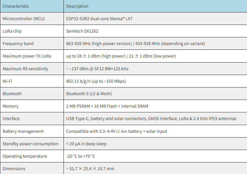
In my previous article on the Heltec LoRa 32 V4 test result, I subjected this Meshtastic node to a description, but more importantly, to a series of rigorous technical tests: radio architecture, transmission power, reception sensitivity, energy consumption, and real-world performance. I demonstrated that this platform, equipped with an ESP32-S3R2 microcontroller and an SX1262 chip with an external amplifier, can achieve useful power levels (up to ~27 dBm in a configuration compliant with European standards) while maintaining relatively low power consumption during standby and wake-up phases.
These results showed that the V4 performs well in terms of connectivity and Meshtastic stability , and that it provides a reliable foundation for network deployments. However, its "experimental" form factor and ergonomics remain those of an electronic assembly board: if I want to use it in the field, in mobile situations, or for practical applications, certain limitations therefore arise.
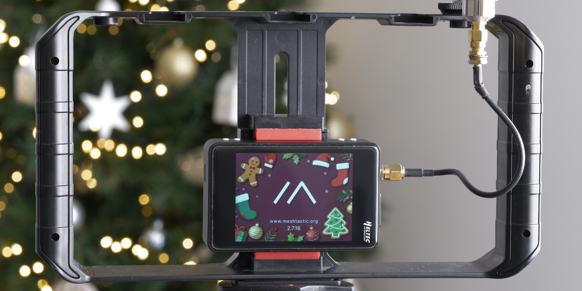
For this purpose, the Heltec WiFi LoRa 32 Expansion Kit exists: it doesn't modify the V4's performance, but offers a version adapted for practical and mobile use, with a more accessible interface and improved ergonomics. This article presents this kit ( Unboxing ) focusing on its field utility, ergonomics, interface, and concrete benefits for a Meshtastic user . Its role isn't to add obscure features: it serves to transform a high-performance module into a mobile tool , ready to be carried in a backpack, deployed on a ridge, a high point, an improvised mast, or a suitable tripod.
This article therefore presents this kit by focusing on its field utility, its ergonomics, its interface and the concrete benefits for a Meshtastic user .
The first thing that strikes you about the Expansion Kit is its ability to be used immediately, without complex installation . The integrated battery allows for several hours to a full day of operation without an external power supply, and the rigid yet lightweight casing makes the node easily portable with its belt clip. It can be slipped into a bag, placed on a flat surface, or held in your hand to control the Meshtastic network. This portability transforms a technical module into an operational tool , usable right out of the bag. Like its competitors, it boasts a relatively compact size and weight.
One of the major advantages of the Expansion Kit is that it allows the use of a Meshtastic node without constantly relying on a computer or phone . The kit actually offers three complementary interaction methods , covering both rapid diagnostics and routine operation.
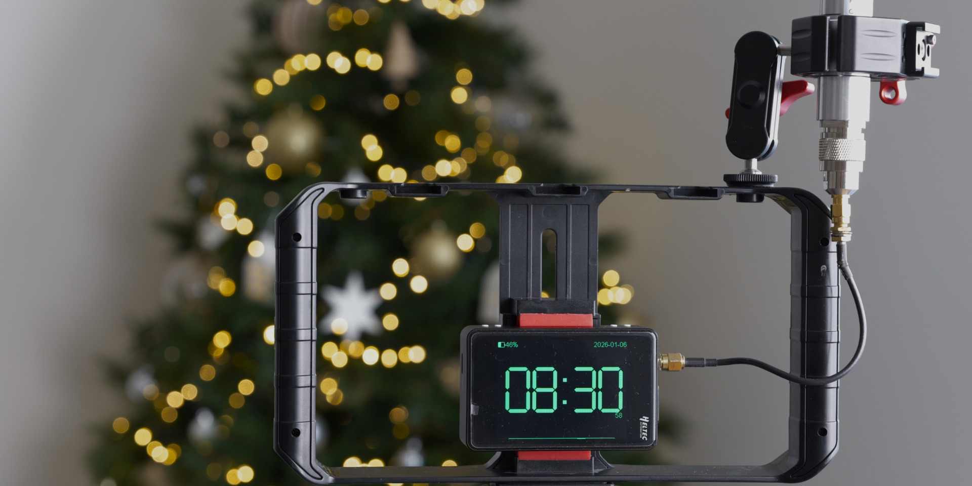
1️⃣Standalone use with the native firmware interface
The Meshtastic firmware already includes a minimalist interface, designed to work:
with the physical buttons , . with touchscreens , depending on the type of screen, . via short presses / long presses to access essential functions. . This interface allows you to: without any further assistance.
check the node status, . check the network connection, . display simple information (messages, neighbors, radio status), . trigger certain basic actions.
In practice, this addresses a simple need: To be able to control the node and understand what it is doing , even if the smartphone remains in the bag or has no battery.
It's not visually spectacular, but it's reliable, understated, and sufficient for most usage scenarios.
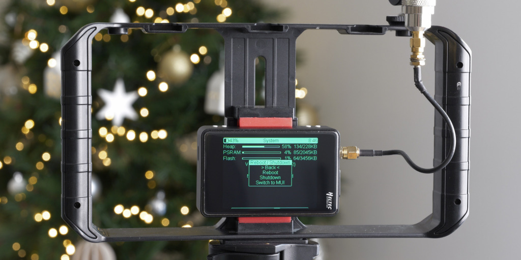
2️⃣MUI: A richer, fully touch-sensitive interface
The MUI (Meshtastic User Interface) mode provides an additional layer, more modern, more readable and designed for the kit's touch screen.
The display now reads:
more graphic,. better structured,. closer to a small embedded application.
MUI allows, in particular:
smooth navigation between menus,. a clearer visualization of nodes and messages,. a better understanding of network activity.
The benefit is twofold:
Immediate understanding : we “see” what is happening more quickly.. Field decision : we can decide to move the node, adjust a position, or simply check that everything is rotating correctly.
In practice, MUI truly transforms the kit into a portable monitoring terminal , usable without mediation.
3️⃣ Connexion Bluetooth via l’application smartphone
Third option: Bluetooth connection with the Meshtastic app. Here, the kit becomes the heart of the system, but it relies on the smartphone for:
manage messages,. configure the node,. view history,. manipulate advanced settings.
The advantage is obvious: When you need to go further, everything is done from the application, wirelessly, and without having to plug anything in.
Bluetooth therefore allows:
a finer configuration. comfortable typing. and extensive control.
The kit retains its autonomy, but the smartphone becomes a control tablet .
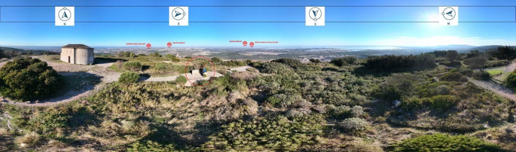
To put the Heltec WiFi LoRa 32 Expansion Kit to the test , I wanted to move beyond theory and conduct a real-world trial. So I climbed to a high point, around 200 meters above sea level, located approximately ten kilometers from one of my modules. The objective was simple: to verify whether, under favorable conditions, the Heltec V4 equipped with the expansion kit remained truly usable for significant long-distance communication.
The result was more than convincing. From this elevated position, I was able to communicate easily with my residential module. Messages were transmitted quickly, without any unusual delays, and the communication remained perfectly smooth. This confirms that with minimal clearance, the system's practical range becomes very impressive, even without an optimized fixed installation.
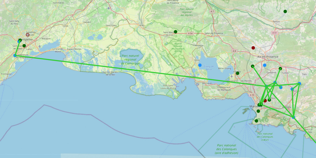
But the experiment didn't stop there. By observing the grid, I also began to detect several distant nodes. From the Hérault region, I saw modules appear located in the Vaucluse, the Gard, and the Bouches-du-Rhône.
This is not a scientific measurement campaign, but rather a concrete indicator : The Meshtastic/Gaulix network exists, it is alive, and it becomes visible as soon as you gain a little altitude.
These observations highlight one key point: the range is highly context-dependent. A few extra meters of altitude radically change the experience. One becomes not only able to communicate with a module some ten kilometers away, but also to perceive the larger network structure—in this case, the Gaulix radio mesh —as it operates and propagates across the territory.
Conclusion: A powerful platform, finally usable in the field
With the Expansion Kit, the Heltec WiFi LoRa 32 V4 takes on a whole new dimension. In my previous article, I demonstrated that this module was already remarkable from a technical standpoint: high transmission power, efficient radio sensitivity, stability, and reasonable power consumption. In other words, the V4 has a real performance reserve, capable of supporting Meshtastic exchanges in sometimes demanding environments.
What the kit offers isn't "more power" or "more range." The radio itself remains the same, with its inherent qualities. The difference is that this performance finally becomes useful for everyday mobility .
Thanks to the casing, integrated battery life, onboard interfaces, and Bluetooth, I can truly utilize this radio capability in the field: testing, observing, exchanging information, climbing to a high point, and understanding how the network behaves. It's no longer just a laboratory module; it's an operational tool.
In the future, I will continue testing — particularly with finer measurements (RSSI, SNR, link regularity) and in varied environments.
P.S.
The original article was written by a French user, and we have obtained permission to republish it.
If you would like to read the original article in French, you can view it here.
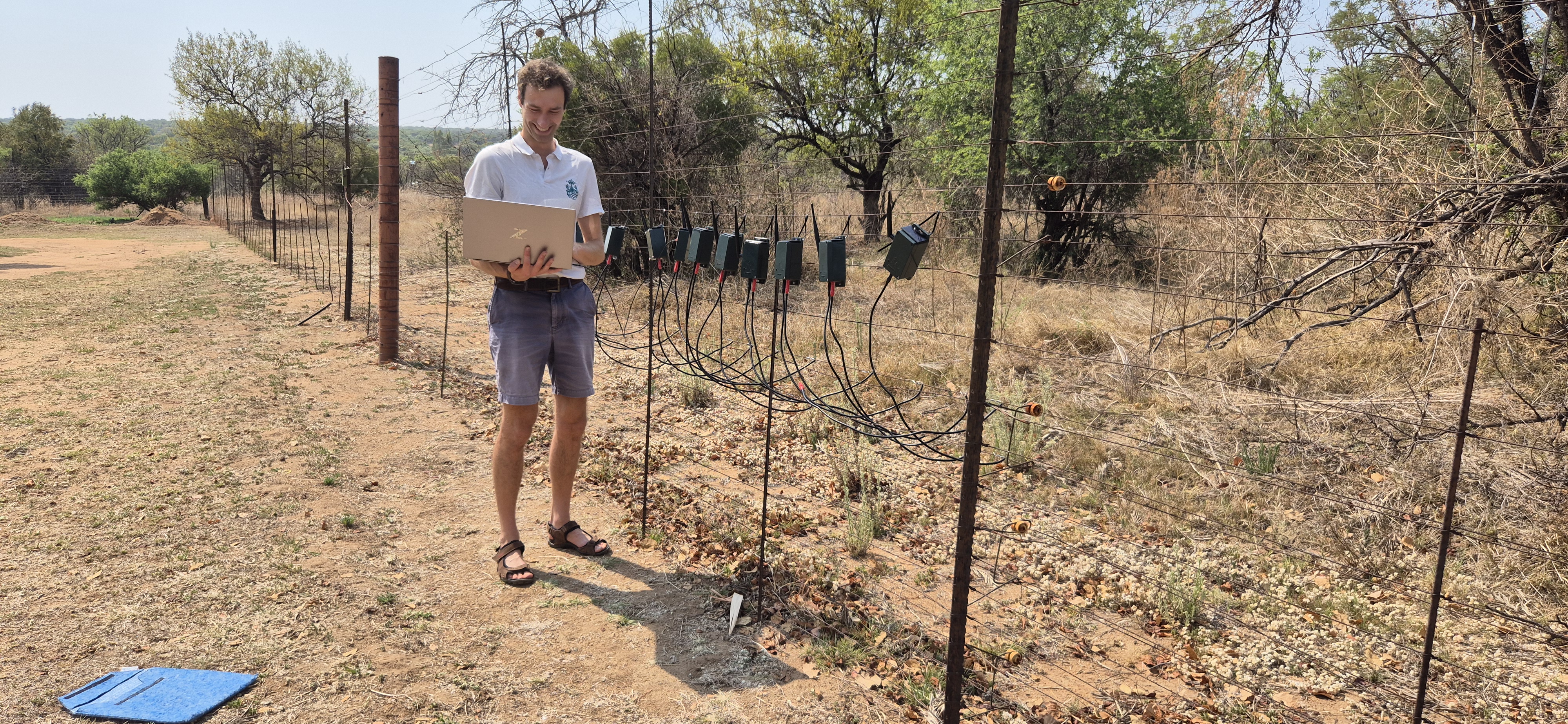
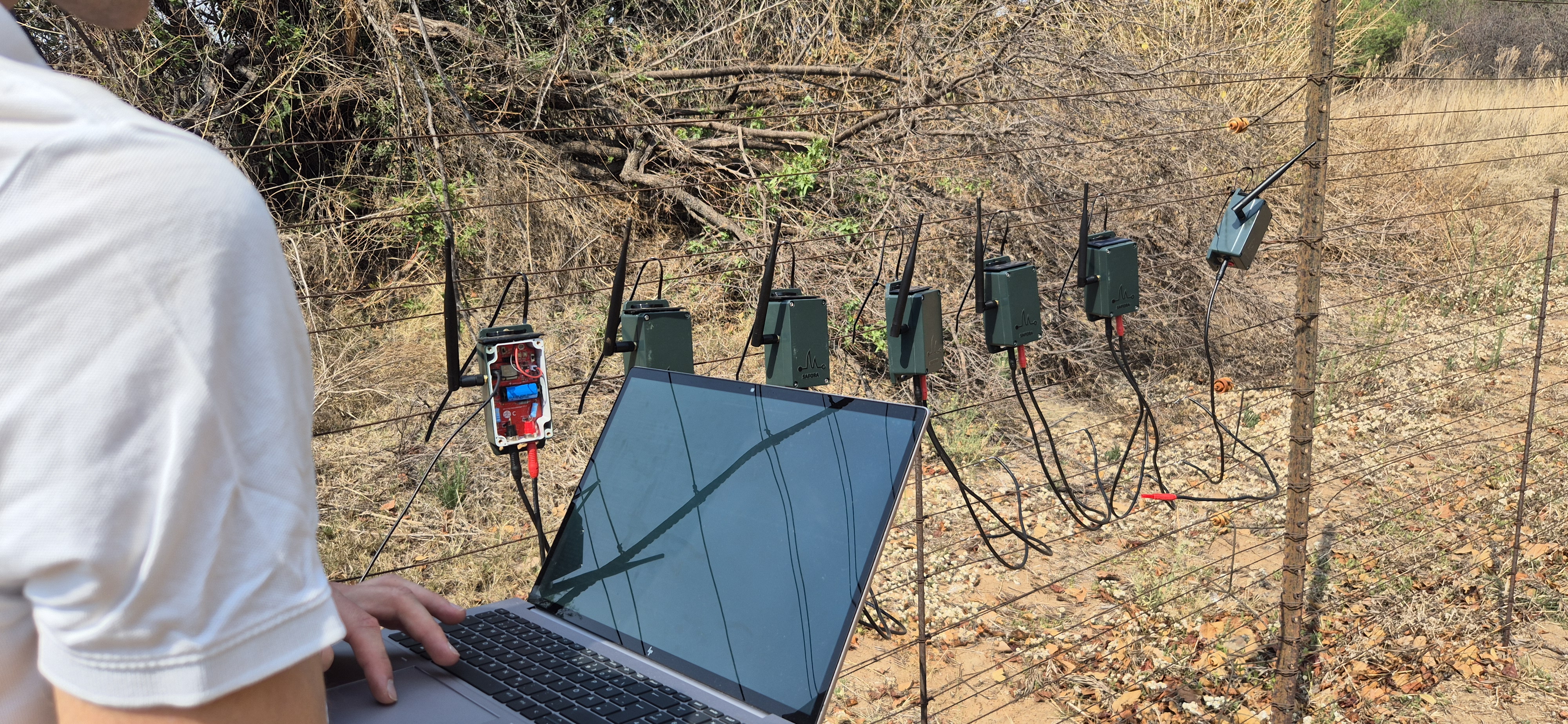
The Dinoken Wildlife Reserve in South Africa is a vast area where rhinos, elephants, antelopes, and other wild animals roam freely. However, the presence of poachers has recently posed an increasing threat to their safety. Poachers often cut through the reserve's iron fence at night, and the damage isn't discovered until the next morning—by which time the precious wildlife is often already dead. Rangers struggle to track poachers and detect gunfire, making it difficult to stop poaching before it occurs.
To address this problem and curb poaching at its source, WILD, in collaboration with SPOTS and the Dinoken Wildlife Reserve, developed a fence intrusion detection system called FenceRanger. This low-power, long-range communication system is specifically designed for large wildlife reserves. They installed one system every 1 to 2 kilometers along the reserve's motorized outer fence, continuously monitoring voltage changes.
If the fence is breached, the system sends an alert to rangers' devices via a LoRa network within approximately 3 seconds—even indicating the exact location of the damage. It also connects to WILD's AirRanger drone (a fully automated fixed-wing surveillance drone), allowing rangers to intercept poachers before they approach endangered animals. The device can even detect minute vibrations in the fence; if someone cuts a wire or knocks down a fence, the signal is transmitted directly to the ranger's screen via their self-built LoRa network.
The system is solar-powered, allowing it to operate autonomously. It operates 24/7, regardless of the environment's harshness—from the frigid winter nights to the scorching heat of South African summers, which can exceed 40 degrees Celsius.
This system has revolutionized the way rangers work. Previously, they could only patrol and investigate after incidents occurred; now they can prevent problems from happening in advance. Dealing with poachers is also safer due to the reduced unknown risks. Furthermore, fence repairs have become much easier—the system accurately informs rangers of the location of damage and the parts requiring immediate repair.
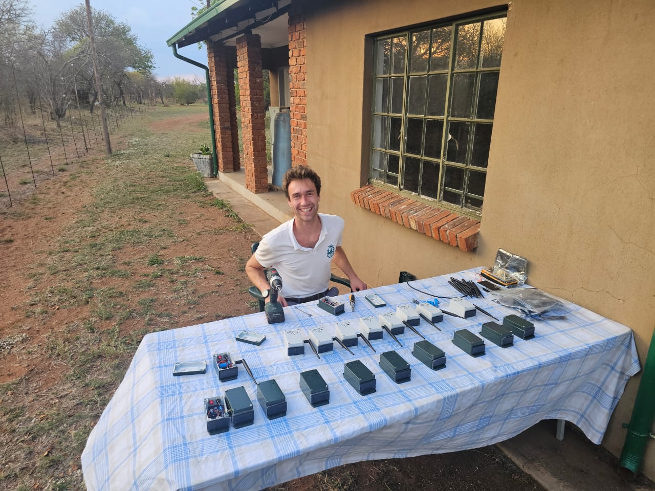
Back in December 2024, they installed the first eight test systems at the Dinoken Wildlife Sanctuary. Over the past year, they deployed 40 FenceRanger devices there, all of which passed reliability testing in real-world field environments. They also built a complete LoRa communication network covering the entire area, and the project is gradually transitioning from the testing phase to full deployment. The plan is to achieve full coverage of the 160-kilometer-long fence of the Dinoken Conservation Area by early Q2 2026. In the future, they hope to use Dinoken as a first large-scale example to promote this system to other protected areas around the world, allowing more wildlife areas to benefit from this technology.
In developing FenceRanger, they followed five key principles: low power consumption, long-distance communication in the absence of mobile networks, hardware adaptability to harsh field environments, modular and upgradeable PCB structure, and affordable pricing for use in large protected areas.
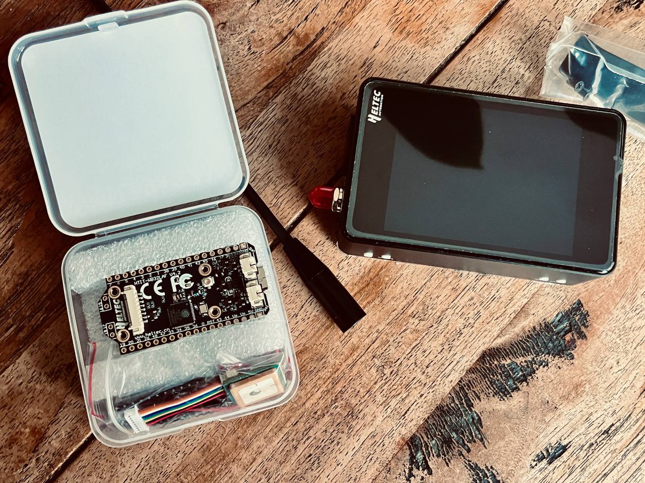
Heltec developed the core component of the system—the HT-CT62 (ESP32-C3 + SX1262 LoRa) module. It serves as the system's "communication heart," supporting a three-dimensional protection architecture that includes ground detection, cloud-based early warning, and aerial coordination, thereby meeting all key design objectives. The ultra-low-power device continuously monitors the fence and, upon detecting anomalies, sends an alert with location information via the LoRa network. Meanwhile, the AirRanger drone transmits real-time aerial footage to assist rangers.
The system uses wireless LoRa networking, eliminating the need for complex wiring. This significantly reduces fence setup time, saves initial costs, is highly adaptable to field environments, reduces the need for equipment maintenance and replacement, and lowers long-term operating costs.
FenceRanger allows rangers to receive alerts within seconds and work in conjunction with the drone, shifting from "remedial" to "preventative" measures, making responses faster and safer. The next version of the system will utilize the WiFi LoRa 32 (V4) platform, improving communication while maintaining low power consumption. Its modular design means rangers can update firmware and upgrade basic functions without replacing all hardware.
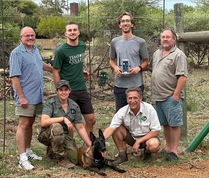
WILD and Heltec state that FenceRanger fills a gap in wildlife conservation technology. Heltec provides robust and cost-effective technical support to organizations like WILD, making technology accessible and sustainable, lowering the barriers to use, and creating a virtuous cycle between technology and practical application.
The project's larger goal is to protect all life, prevent habitat fragmentation, and stop biodiversity loss. This replicable and scalable technology aims to become a global model for wilderness conservation—helping technology and nature coexist harmoniously.
For some time now, we've been exploring the potential uses of Meshtastic and how this type of network can enhance our autonomy. To delve deeper, it's essential to examine the hardware that makes these communications possible. The Heltec LoRa 32 V4 is one of the newcomers to the market, and it deserves to be put through its paces.
The goal here is not to offer a quick opinion, but to understand what this node truly brings to the table: radio architecture, transmission power, sensitivity, power consumption, thermal behavior, and results obtained in the field. We will compare the technical specifications with real-world applications to determine under what conditions this module can become a relevant choice for a resilient Meshtastic network.
In other words, we will test, measure and analyze (with enough technical expertise to inform decisions, but without unnecessarily complicating things).
The Heltec V4 uses the Semtech SX1262 radio chip paired with an external power amplifier ( PA GC1109 ). This combination theoretically allows it to reach up to 28 ± 1 dBm on the European LoRa band, a significant improvement over older modules based on the SX127x series with a typical output power of 21 ± 1 dBm . The theoretical advantage of this architecture is the ability to transmit over longer distances when needed, while maintaining very low power consumption when the equipment is in standby mode.
In practice, the external amplifier only really consumes power during high-power transmissions; as long as the node is listening or in standby mode, the energy demand remains moderate. However, it should be kept in mind that regularly transmitting at 27 dBm increases power consumption and can cause some internal heating of the module, which may temporarily affect observed values such as RSSI or SNR ( RSSI simply indicates how strong the signal is at the antenna, while SNR shows how well it stands out from the noise. If either one degrades, the communication becomes less reliable).
Where the SX1262 chip also excels is in signal quality. Its more precise oscillator and reduced phase noise improve frequency stability and make communications more reliable, even in environments where obstacles degrade reception. This is where another key component comes in: the LNA (Low Noise Amplifier). Unlike the power amplifier, which is used to "speak louder ," the LNA is located on the receiving side and is used to "hear better ." It amplifies very weak signals while adding as little noise as possible, which improves the overall sensitivity of the receiver and increases the chances of decoding distant or weak messages. In other words, the PA helps to reach further when transmitting, while the LNA enhances listening capabilities (both contributing to a more stable effective range).
The SX1262's flexibility also allows for easy adjustment of radio parameters, enabling a balance of range, throughput, and power consumption depending on the scenario ( Meetstastic Presets ). Its very fast switching between receive and transmit improves network responsiveness and reduces collisions, while its sensitivity, which can reach down to approximately -148 dBm in certain configurations, allows it to pick up extremely weak signals. In theory, all of this translates to better range and fewer lost packets , provided that attention is paid to the heat generated at high power and that real-world performance is validated through field measurements.
The Heltec V4 is based on a separate radio architecture for reception and transmission, optimized for range and reliability.
Reception (RX):
Low noise amplifier (LNA) dedicated to reception. Theoretical sensitivity SX1262: up to –148 dBm (SF12 / BW125 kHz). Practical effect: better reception of weak signals and more stable communications.
Emission (TX):
SX1262 base power: up to 22 dBm . Fixed hardware attenuation: approximately -17 dB . External amplifier: PA GC1109 . Maximum advertised power: up to 28 dBm (depending on settings and conditions). In France, the maximum must not exceed 27 dBm ( 500 mW ERP = 27 dBm EIRP ).
2.1 Analysis of the energy consumption of the Heltec V4
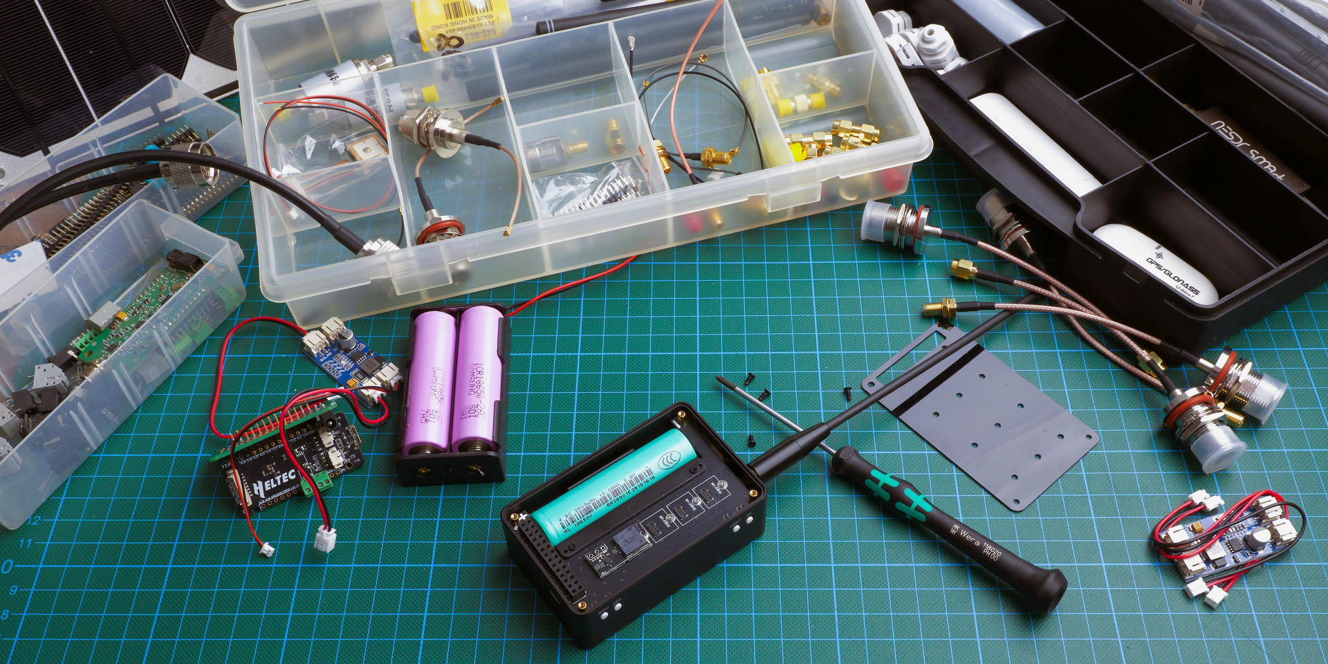
Following a series of comparative tests carried out both via USB-C and via the Vin battery input (with 2 Li-Ion model 18650 batteries in parallel), with a strictly identical configuration:
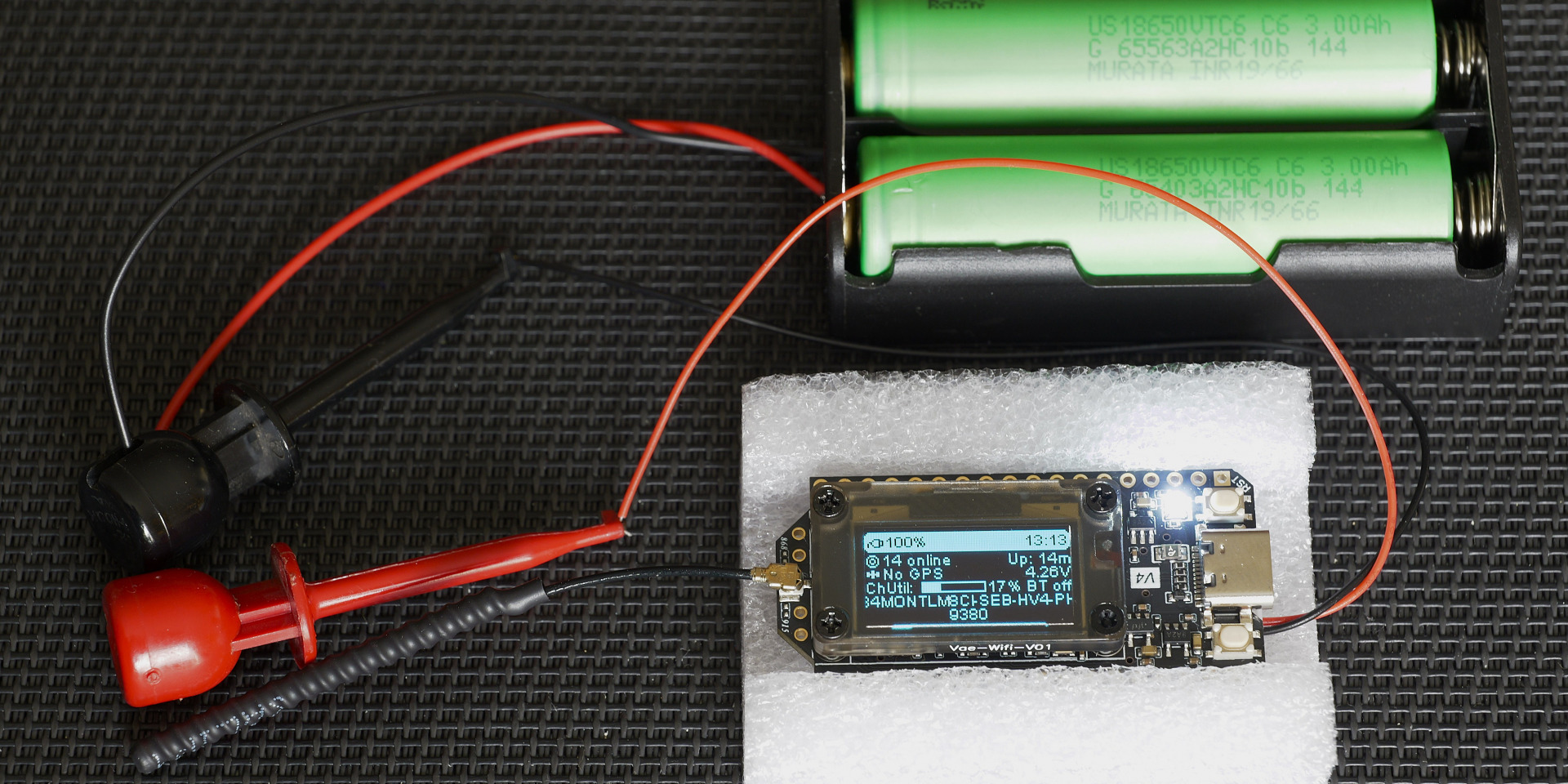
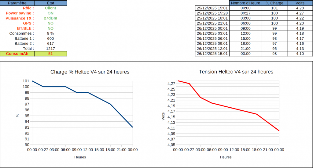
Gaulix configuration (LM, SF:11, CR:4/8, BW:125kHz) Customer Role Power Saving activated. Transmission power set at 27 dBm, GPS declared as NOT_PRESENT Bluetooth disabled .
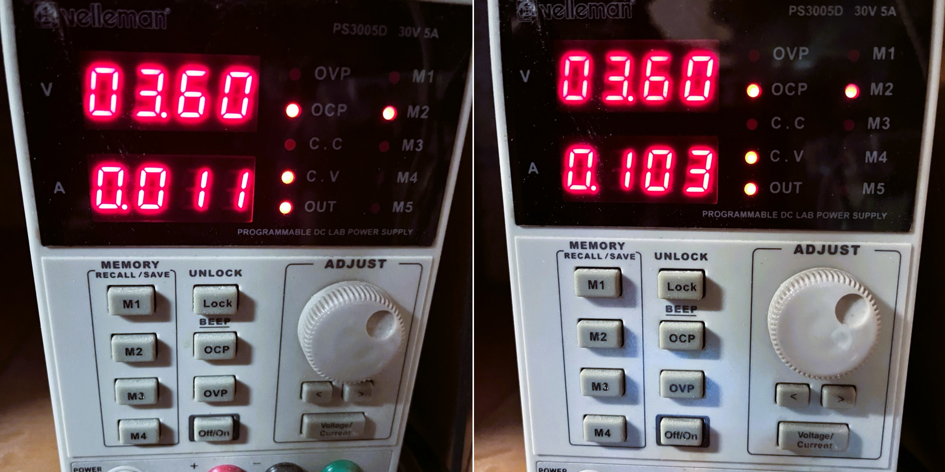
Once the test conditions were stabilized and reproducible, laboratory measurements revealed a floor current consumption of approximately 12 mA in deep standby . During radio standby, the consumption exhibited transient spikes to approximately 115 mA for about ten seconds , corresponding to the system's wake-up and the LoRa transceiver's reactivation.
During transmission, with the power set to 27 dBm, current draw becomes significantly more pronounced, with peaks approaching 1 A for approximately one second . This behavior is consistent with the activation of the power amplifier (GC1109) and the characteristics of the SX1262 when the RF stage is operating at full power.
After 24 hours, the Heltec v4 node in the minimalist configuration mentioned above:
The goal was to measure the cumulative weighted energy consumption of the Heltec V4 over 24 hours during its various phases: deep sleep, receive, and transmit. This consumption is heavily influenced by the duty cycle and radio conditions, including retransmissions, collisions, and acknowledgments (ACKs). It's important to note that the node was naturally exposed to Meshtastic/Gaulix traffic , relayed by my MQTT gateway, which adds a real and dynamic context to the measurements. This approach provides a practical view of average consumption under usage conditions similar to those of a local mesh network.
I ran another series of tests with Bluetooth enabled. During my previous tests, the difference between Bluetooth enabled and disabled seemed unusual. To eliminate any doubt, I therefore ran a new complete batch, this time letting the Heltec V4 reach its breaking point and reboot.
It appears that below 3.45V , operation becomes erratic: a slightly high current draw (acknowledgment, telemetry, RF burst, etc.) is enough to trigger a reboot of the ESP32. In my specific case, the reboot occurred at 3.40V , or about 18% battery charge , after 46 hours and 40 minutes of continuous operation.
P.S.
During this period, the actual capacity used was approximately 4429 mAh , corresponding to an average consumption of around 95 mA . This is roughly double the consumption measured with Bluetooth disabled , confirming the significant impact of BLE on energy consumption.😊
Operational context of the test
Power supply: 2 x 18650 3000 mAh batteries in parallel Bluetooth: enabled permanent exhibition at my MQTT gateway ( Fr_Blabla ) active periodic telemetry approximately a dozen BLE connections approximately thirty LoRa TX messages
In summary: Bluetooth remains usable, but its energy cost is real. For long-term battery deployment, it should be considered a premium service, to be activated only when needed.
2.2 Measurement of effective power
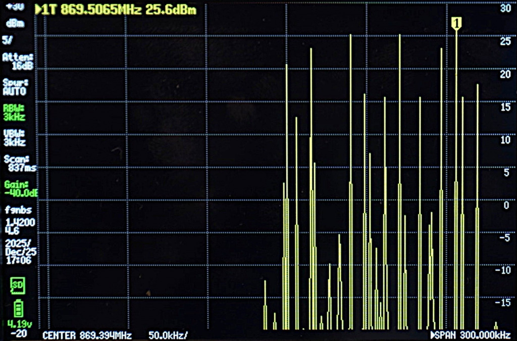
To measure the actual power emitted by the Heltec V4, I used a TinySA Ultra Plus spectrum analyzer with a 40 dB / 10 Wmax attenuator inserted between the transmitter and the device to protect it from an excessively strong signal. The screenshot below shows a measured power of 25.6 dBm , with an accuracy of ±2 dBm. It also shows the power peaks corresponding to the module's actual emissions , allowing for a concrete visualization of the signal dynamics during transmissions and verification of its behavior under real-world conditions.
Considering the calibrated reality of the attenuator and the margin of accuracy of the analyzer, with this measurement, the officially announced power level can be considered real.
P.S.
Competitive position: Today , on the market, the Heltec V4 is one of the few Meshtastic nodes offering such high output power . No other module certified for Europe combines both Meshtastic compatibility and this level of transmission power, making the Heltec V4 the preferred choice for those seeking a node that is both high-performing and compliant with existing standards.
Through measurements and tests, the Heltec V4 is gradually establishing itself as a credible platform for deploying autonomous Meshtastic nodes powered by battery and solar panels. Despite its notoriously power-hungry ESP32 microcontroller and an RF stage reaching 27 dBm, its energy consumption remains surprisingly manageable. Sleep phases, radio wake-ups, and transmission peaks follow a reproducible pattern, allowing for more confident prediction of actual power consumption and thus proper sizing of the power supply chain.
note
As an order of magnitude, going from a node configured at 22 dBm to a Heltec V4 at 27 dBm does not represent “a small step up”, but about three times more emitted power .
In this context, the Heltec V4 is no longer limited to purely experimental use. When properly configured, installed correctly, and connected to a coherent power system, it can reliably fulfill its role as an infrastructure node while providing robust radio coverage. Adding an external, Meshtastic-compatible RTC clock, such as the PCF8563, would further enhance this capability: by stabilizing time management during deep sleep phases, it optimizes wake-ups, avoids unnecessary activations, and directly contributes to preserving battery life.
In summary, what appears on paper as a powerful but power-hungry card turns out, in reality, to be a platform surprisingly well-suited to off-grid scenarios (provided that energy is approached as a component of the system in its own right, and not as a simple accessory).
Let's take a concrete example. Imagine a Meshtastic node based on a Heltec V4, installed outdoors, and powered by a small 10W solar panel combined with two 21700 Li - ion batteries (e.g., 2 x 4800mAh) mounted in parallel.
In this configuration, the two 21700s act as a true buffer. Their higher capacity and low internal resistance allow them to easily handle the near 1 A peaks generated during 27 dBm transmissions, while preventing the sudden voltage drops that can cause the node to restart. Meanwhile, the 10 W panel doesn't attempt to power the system in real time; it recharges gradually, as sunlight becomes available.
On a typical day, solar production can be sufficient to replenish the energy consumed, especially if the software configuration limits unnecessary wake-ups and optimizes standby periods. And when the weather deteriorates—overcast skies, snow, partial shade—the dual 21700 battery pack ensures continuity, significantly delaying the drop to the critical threshold around 3.2V. The system then functions as a coherent whole: the panel recharges gradually, the battery absorbs fluctuations, and the node maintains its radio availability.
Because the cells are connected in parallel, the voltage remains stable, the solar controller operates within a comfortable range, and the average depth of discharge decreases, thus extending battery life. This example illustrates a simple yet robust architecture: a Heltec V4, two 21700s, an MPPT , and a 10W panel form a realistic basis for a truly self-sustaining Meshtastic infrastructure node.
The measurements presented here constitute a first step. They will be supplemented by real-world field tests to compare theoretical and laboratory data with the constraints of the outside world. Furthermore, a dedicated article will soon be published on the integration of the Heltec LoRa 32 V4 into the "Mobile" expansion kit , the WiFi LoRa 32 Expansion Kit ( Heltec link ), allowing exploration of mobile applications and the hardware expansion possibilities offered by this module.
A unit that expresses power in milliwatts on a logarithmic scale. It describes the electrical energy actually sent by the device to the antenna .
0 dBm = 1 mW 10 dBm = 10 mW 20 dBm = 100 mW: Each +10 dBm multiplies the power by ten . This is the base value from which everything else is calculated.
The unit expressing the gain of an antenna relative to an ideal isotropic antenna . The dBi does not create any additional power ; it directs and concentrates energy in certain directions to improve effective range. A high-gain antenna is not "more powerful," it is more directional .
RSSI – Received Signal Strength Indicator for LoRa
The strength of the signal actually received by the device, expressed in dBm (always negative). This is the “perceived power” on the receiving side.
-30 to -60 dBm : excellent -60 to -90 dBm : acceptable / reliable -90 to -120 dBm : reception limit, strongly dependent on the spreading factor and the band used
Ratio between the received signal and the surrounding noise, expressed in dB. Unlike other radio technologies, LoRa can decode a signal even with a negative SNR , thanks to its chirp spread spectrum (CSS) modulation .
Typical SNR LoRa beach:
0 dB : very good signal 0 to -10 dB : weak but usable signal -10 to -20 dB : decodable according to the spreading factor (SF) < -20 dB: almost impossible
Example minimum SNR per SF (Semtech SX126x): SF7 → –7.5 dB | SF8 → –10 dB | SF9 → –12.5 dB | SF10 → –15 dB | SF11 → –17.5 dB | SF12 → –20 dB
The higher the SF, the better LoRa can recover a signal buried in noise.
The Spreading Factor defines the number of symbols used to encode each bit in the LoRa CSS modulation.
The higher the SF , the more each bit is spread over several symbols, which lengthens the frame duration . A longer frame increases the range and allows decoding of signals even with a negative SNR , but reduces the throughput . Typical values range from SF7 to SF12 , with SF12 offering the maximum range but the minimum throughput.
The EIRP corresponds to the theoretical power radiated by the "transmitter + antenna" system. It is calculated as follows: EIRP = Power (dBm) + Antenna Gain (dBi) – losses (cables, connectors).
This is the value used by regulations because it reflects the actual effect of the antenna in space.
An alternative version of EIRP, based not on an isotropic antenna but on a half-wave dipole . In practice, we consider: PAR or ERP = EIRP – 2.15 dB.
The logic remains the same: it is an estimate of the actual radiated power, but with a different reference.
what the device actually emits (dBm), what the antenna does with this energy (dBi), what the other device receives (RSSI), in what “cleanliness” it receives it (SNR, LoRa only), the duration and range of the frames (SF, LoRa only), and what power is actually sent into the environment (PIRE/ ERP).
From a regulatory perspective, most LoRa regions manage devices based on the maximum EIRP.
Application to Meshtastic in band 869.4–869.65 MHz
The region setting in Meshtastic is primarily used to adjust the frequency and duty cycle rules, but it does not limit the module's transmission power. To comply with regulations, you must therefore manually adjust the power based on the antenna and signal loss.
In the European Union, and therefore in France, Decision 2006/771/EC as amended (band no. 54) authorizes:
500 mW PAR = 27 dBm WORSE EIRP
This means that:
If your antenna has a gain of 2 dBi And that your cable loses 0.5 dB → Your module output power should be set to around 25.5 dBm to comply with 27 dBm EIRP.
This project was created as a response to the recurring problem of wildfires in my country, Honduras. Every year, thousands of hectares are lost, and one of the most affected areas is La Tigra National Park. Beyond being a protected biodiversity zone, La Tigra is the main water source for the capital city, so early detection of fire activity is critical.
The project aims to show the viability of a low-cost LoRa-based mesh network capable of monitoring air quality in real time across forested areas. The goal is to detect the early signs of a fire before it becomes large enough to cause irreversible damage.
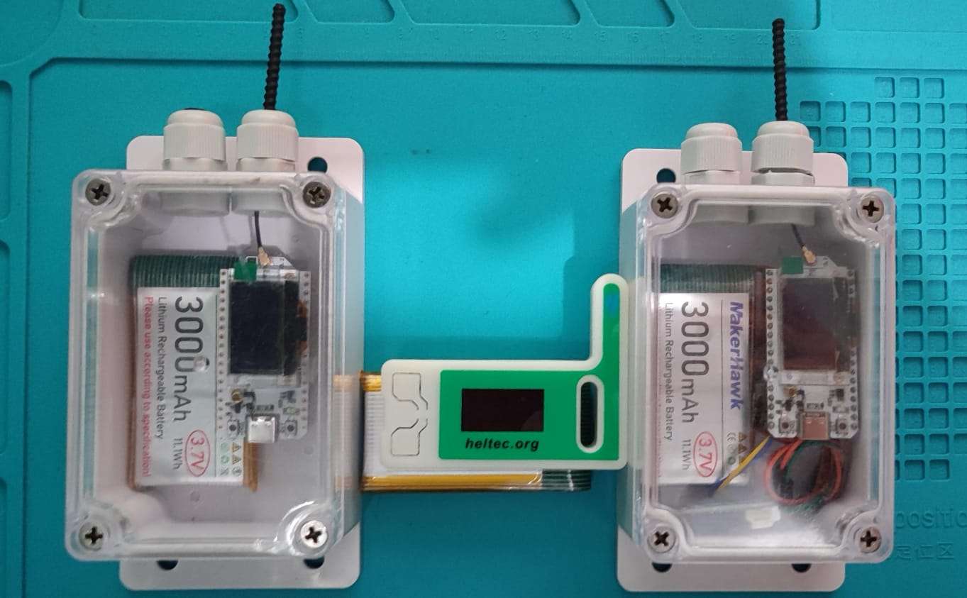
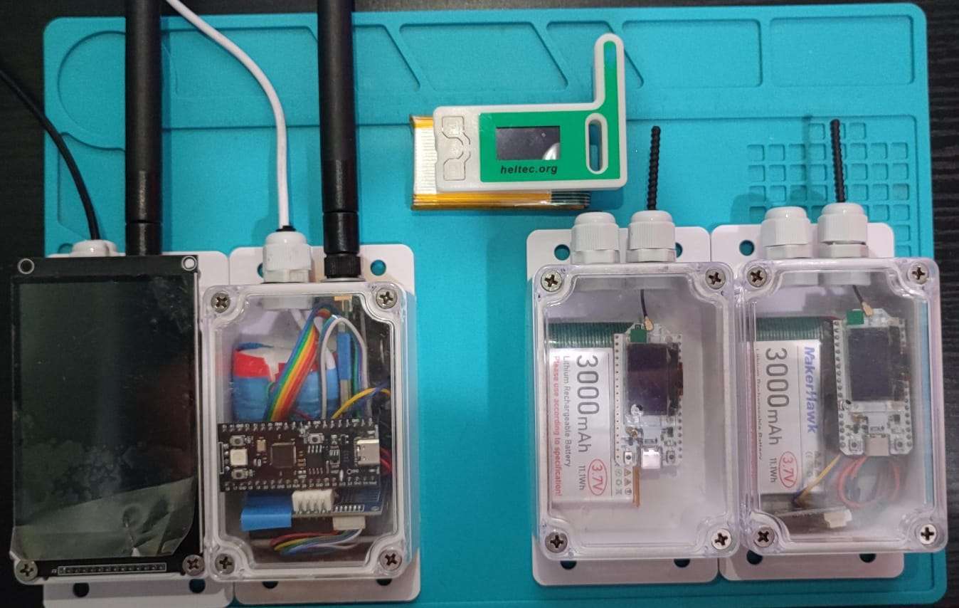
The idea began with an earlier prototype based on an RP2040, an RTC module, traditional LoRa point-to-point communication, and a Sharp GP2Y smoke sensor. The prototype demonstrated that early smoke detection was possible, but it lacked the characteristics needed for a real deployment: energy efficiency, long communication range, and mesh networking. This led to the new design using the Heltec V3 and the BME688 sensor, which better fits the requirements of a forest-scale deployment.
Preparation
Below is the list of items required for the project, with the exact quantities used and the purchase links for replication.
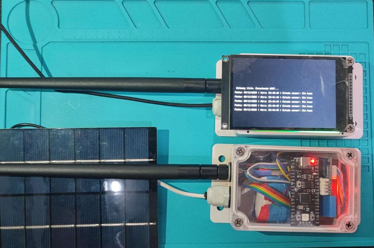
The project uses one Heltec V3 configured as a sensor node, another as a router, and a third as the receiving gateway. Meshtastic version 2.5.4.8d288d5 was used for the sensor node because it allows shorter telemetry intervals required for this application.
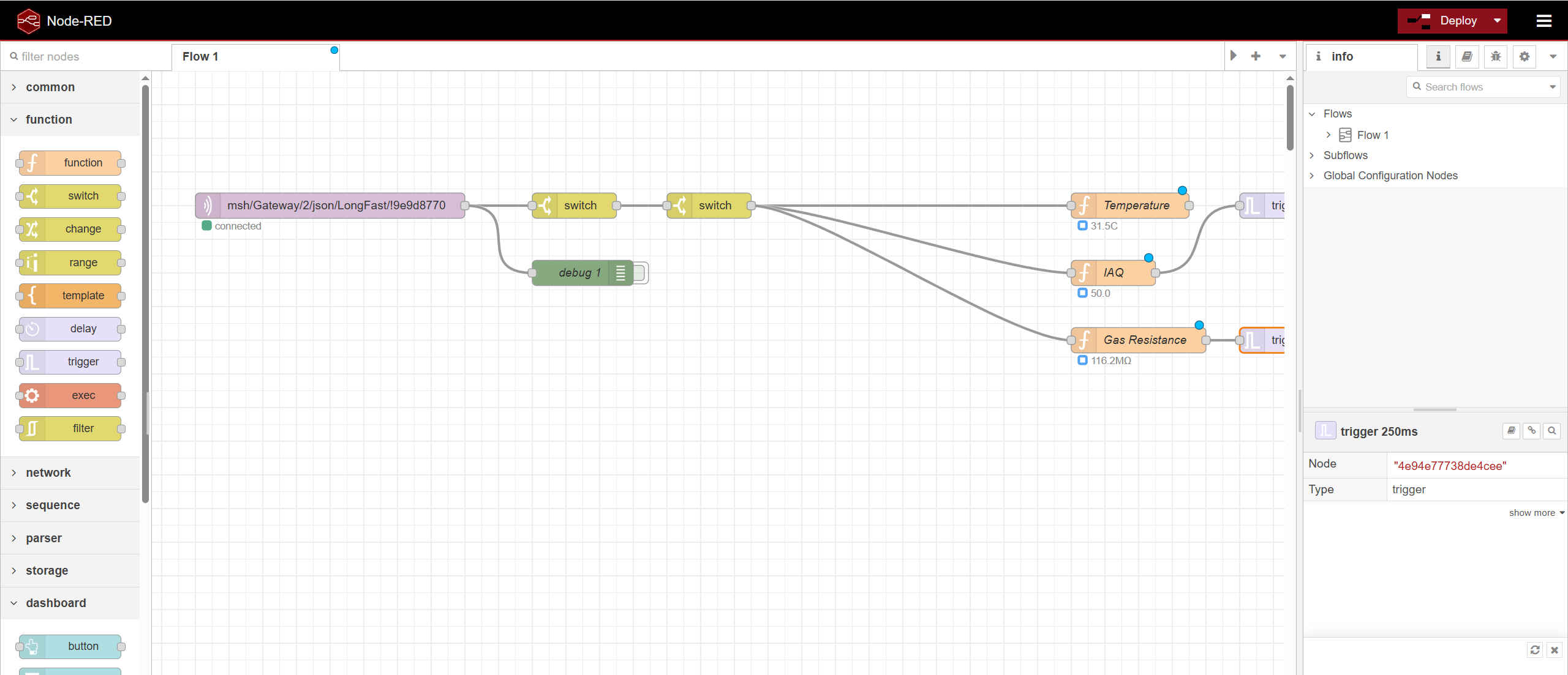
The BME688 sensor is read by the sensor node using the Meshtastic I²C direction pins (GPIO 41 for SDA and GPIO 42 for SCL). The sensor node transmits telemetry over LoRa. The router relays the packets deeper into the mesh, and the gateway node forwards the packets to a local Mosquitto MQTT server. Node-RED processes the incoming data.
Two improvements are proposed for future versions, and these are optional approaches:
Modify Meshtastic firmware to support a pretrained BSEC model on the BME688, trained on clean air and smoke.
Add a secondary microcontroller dedicated to smoke detection logic, sending only the relevant alerts to the V3 via UART.
A third proposal is to replace Meshtastic entirely across the entire system. This would allow the use of a very low-power custom firmware and a communication strategy focused strictly on meeting long-term energy requirements, rather than depending on Meshtastic’s operational model.
Below are the measured average current consumption values:
Router node:
Standby: 11.1 mA
Window after data reception (every 1–3 seconds): approximately 130 mA
During active packet reception: 174 mA
Sensor node:
Standby: 98 mA
During LoRa transmission: 170 mA
All measurements were taken using default Meshtastic roles without deep firmware modifications.
Finished project showcase / Summary
Although the system is still under development, The current implementation demonstrates that BME688 gas measurements, can be transmitted through a local LoRa mesh, and forwards the data to an MQTT server for processing. Although the current implementation is simple, it demonstrates that a distributed private mesh can operate reliably in forest environments to support early detection of fire activity.
The main areas for future improvement include:
Replacing the default Heltec antennas with higher-performance long-range models suitable for forest terrain.
Replacing the Heltec V3 with the Mesh Node T114, which offers significantly better energy efficiency and direct solar-panel support.
Implementing intelligent smoke-detection logic using either a modified Meshtastic firmware or independent microcontroller firmware.
A watchdog-like mechanism that detects silent nodes and automatically triggers a fallback alert if communication is lost.
The Node-RED flow is expected to provide visualization of system states, warnings, and alarms, helping users understand environmental changes in real time and act if needed.
The project shows that early wildfire detection using low-cost mesh networks is achievable and practical. With further optimization and better energy management, these systems can be deployed across large protected areas to help prevent major environmental losses.
December 23, 2025 – As Christmas bells ring in and the New Year approaches, Heltec Automation, a globally leading provider of IoT and open-source hardware solutions, today announced the launch of its annual "Christmas Gifts, New Year Ideas" dual-festival promotion. The campaign will warmly begin on December 24, 2025, and run through January 5, 2026. Designed as a special seasonal gift for the global developer and maker community, this promotion features carefully structured tiered discounts, aiming to help every innovator equip themselves with the ideal "tools for creation" during this festive season and step confidently into their 2026 projects.