Quick Start
This article describes how to deploy HRI-3632 quickly.
Before you enter the configuration mode, please do all operations without power.
Connect to RS-485 Device
- Unscrew the connector as shown below.
-d582205b47ae5cb3810733b9501d1d5d.jpg)
- Put it on the cable of the RS-485 sensor.
-c586a4efddf12421b97a5444a9e93e8a.jpg)
- Unscrew and connect the sensor cable, whose interface is defined as follows.
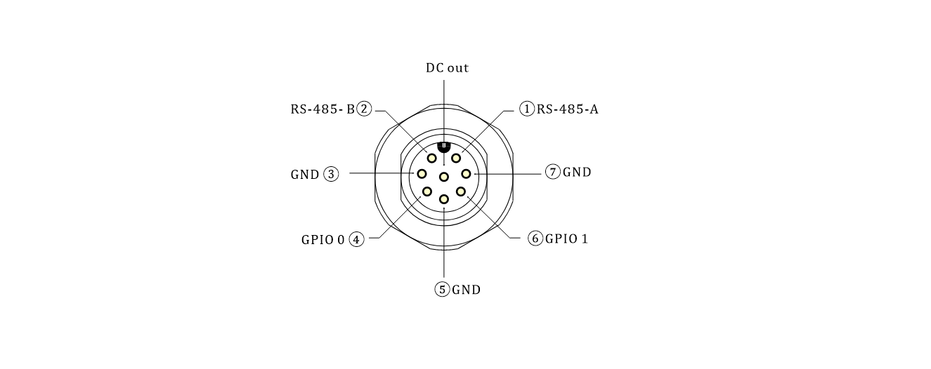
that the counterclockwise direction of each interface has the number corresponding to its pins.
Connect the external power connector
- Unscrew the connector as shown below.
- Put it on the cable of the DC power supply or solar panel.
- Unscrew and connect the sensor cable, whose interface is defined as follows. Choose according to your use case.
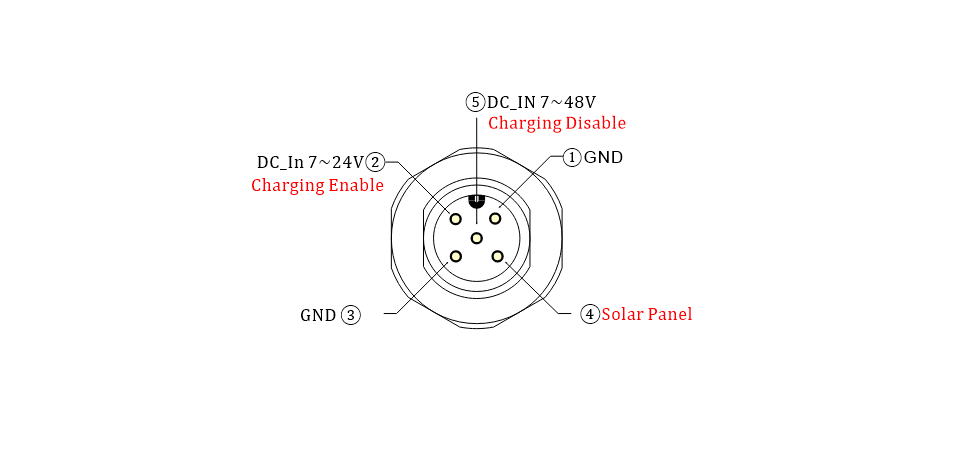
- There is a pin number next to each interface.
DC-IN 7 ~24V can power the device while charging the built-in battery; DC-IN 7 ~48V can accommodate some higher voltage scenarios, but it cannot charge the built-in battery.
Power ON
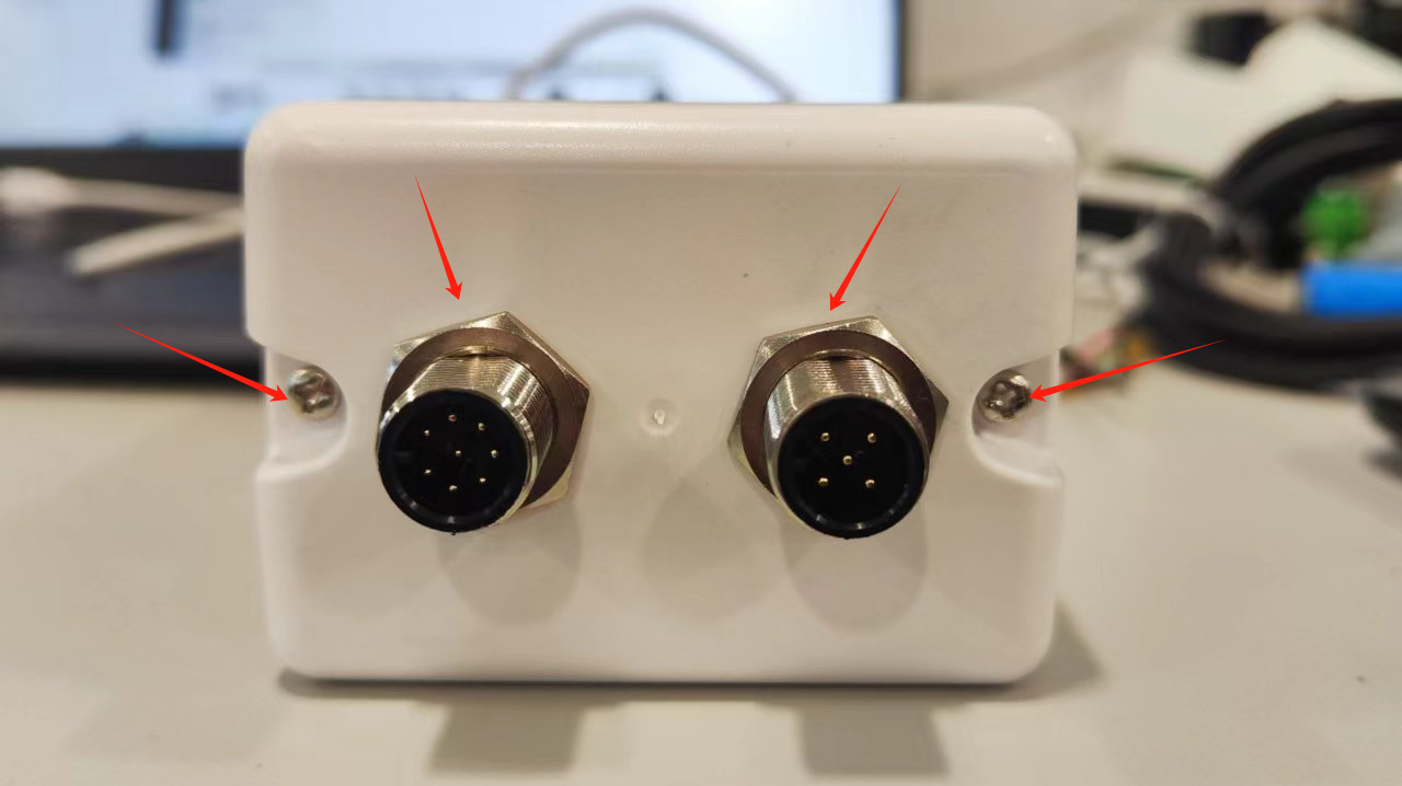
- Unscrew the nuts on the flange seat and the screws on both sides of the cover in turn as shown in the figure.
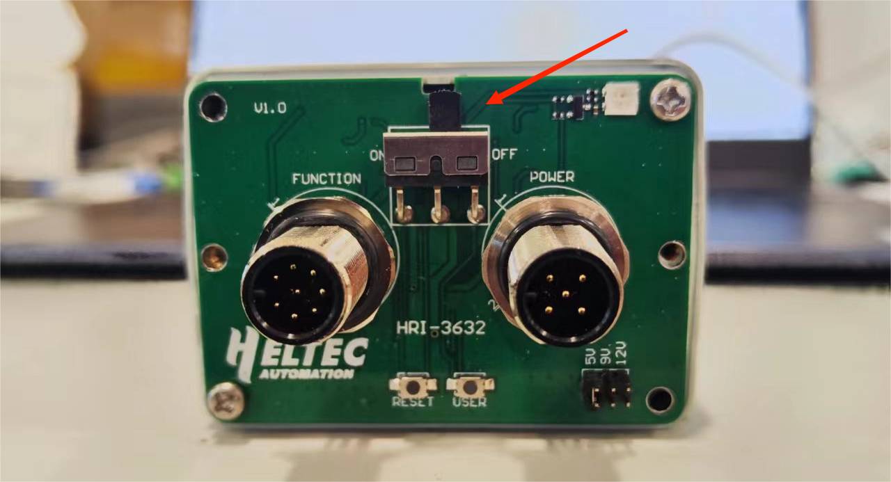
- Turn the switch to
ON, and the green light flashes once, At this point, the device enters the working state.
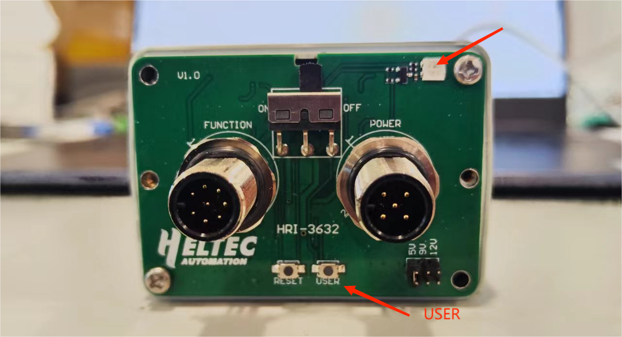
Configuration
- Turn the switch to
ON, Long press theUserkey, the red light is always on, then enter the configuration mode.
The device will automatically restart after 10 minutes in configuration mode.
- Use your phone or computer to find a Wi-Fi hotspot named HRI-3632-XXXX and connect it.
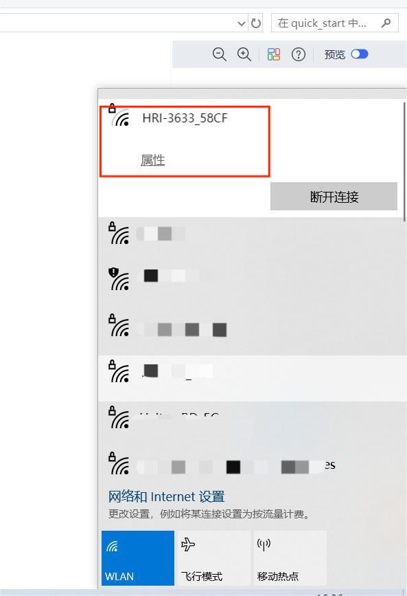
- Type 192.168.4.1 in your browser, and press Enter to take you to the configuration page.
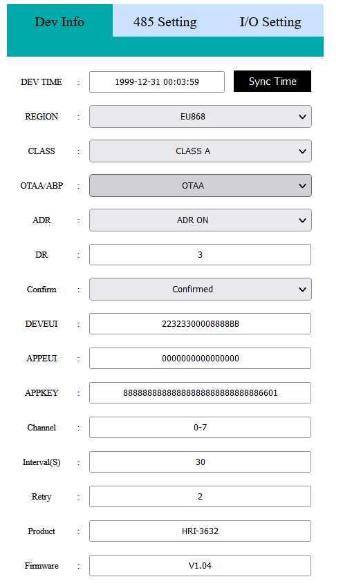
Description of Configuration Parameters
The configuration parameters are defined as follows:
LoRaWAN Parameters
OTAA Mode:
Dev-TimeEquipment time setting and calibrationREGIONLoRaWAN frequency bandCLASSLoRaWAN operation mode, Class A or Class COTAA/ABPLoRaWAN communication modeADRData rate adaptationDRData rate, can be adjusted when the ADR option is turned offCONFIRMUplink receipt confirmedDEVEUIAPPEUIAPPKEYOTAA node parameters, must be consistent across the server.ChannelLoRaWAN channel, different channels should be separated by Spaces, such as "0-7 13 16-23"Interval(S)Period of transitionRetryThe number of retransmission attempts after a failureProductProduct modelFirmwareFirmware versionBatteryBattery level (percentage)SubmitClick Submit after the configuration is completeFirmware UpdateUsed for OTA firmware upgrade
ABP mode
Most are the same as above, but the differences are listed below:
NWKSKEYAPPSKEYDEVADDRABP node parameters, must be consistent across the serverRX1 DELAY(S)Set the time for RX1 to be delayed onRX2 DR typeData rate, you can choose the default or set your ownRX2 DRCan be set when the DR type is customRX2 Freq typeRX2 Frequency band, you can choose the default or set your ownRX2 FreqCan be set when the Freq type is custom
The uplink port is fixed as port 2.
485-Setting Parameters
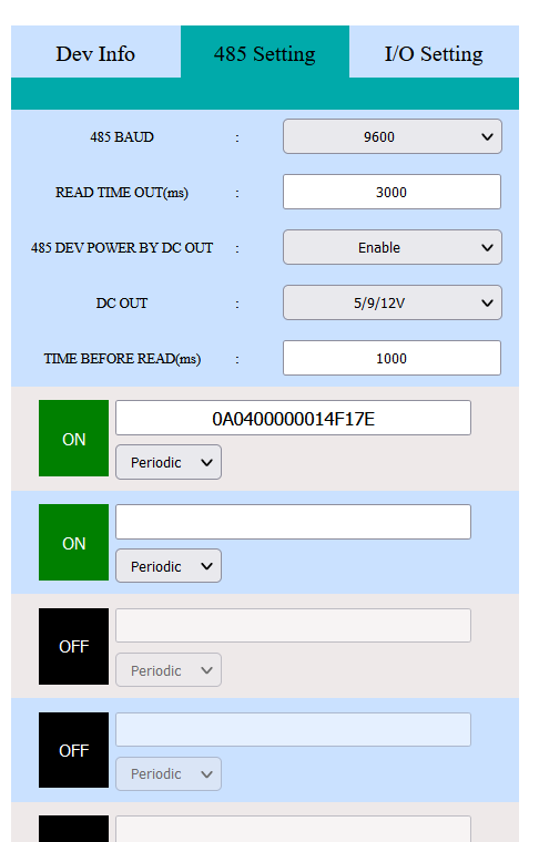
485 BAUD485 baud rate, please be consistent with the terminal.READ TIME OUT.485 DEV POWER BY DC OUTChoosing Enable means powering the device and Disable means not.DC OUTPower supply mode selection:3.3VOutput 3.3V,5/9/12VOut 5/9/12V, select on the device,DC IN (MAX 48V)Power supply access pin DC IN 7-48V, how much is the access voltage, how much is the output,5-24 INPower supply access pin 7~24V, how much is the access voltage, how much is the output.
Time BEFORE READHow much time to power the terminal before it starts reading.ON/OFFTurn on/off an RS-485 instruction.
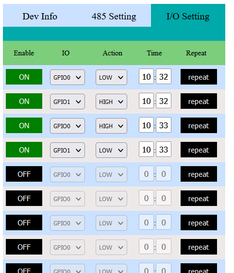
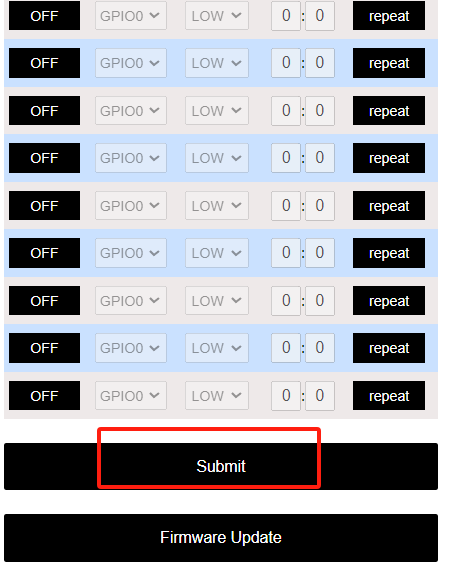
I/O Setting
The Repeat option sets the time (weeks) the GPIO command executes.
After the configuration is completed, Click Submit.
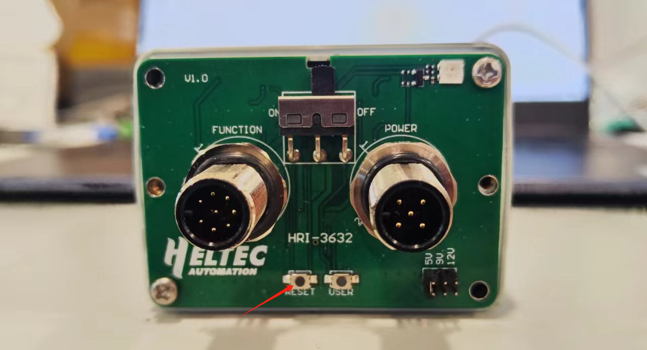
Press the button RESET, The green light flashes once, indicating that the device enters the working mode.
Cover the device, and install the power supply and sensor connector.
Resources
Download Related Resources Wireless Aggregator series product application description