Quick Start
This article describes how to deploy HRI-3633 quickly.
- Power on
- Configuration
- Connecting Valves
- External power supply and Charging
Power on
Unscrew the nuts on the flange seat and the screws on both sides of the cover in turn as shown in the figure.
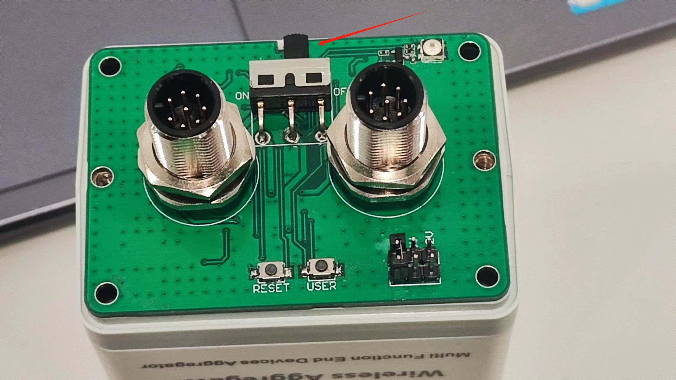
Turn the switch to ON, and the green light flashes once, At this point, the device enters the working state.
Configuration
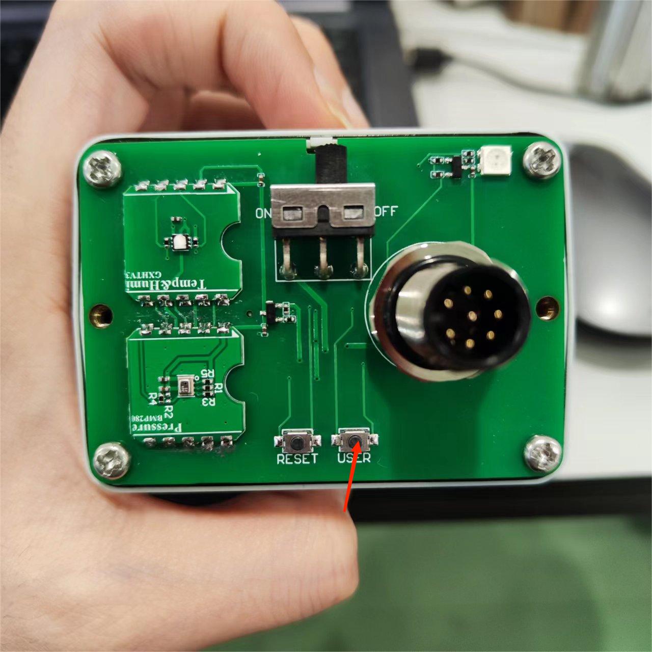
Turn the switch to ON, and the green light flashes once. At this time, the device enters the working mode. Long press the User key, the red light is always on, then enter the configuration mode.
The device will automatically restart after 10 minutes in configuration mode.
In configuration mode, the mobile phone or PC is used to find the WiFi of the device and connect it.
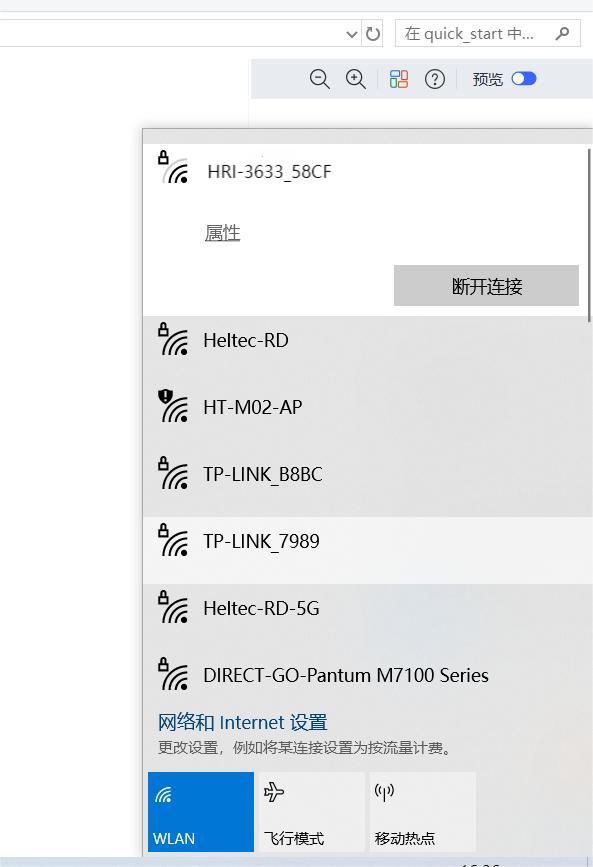
Type 192.168.4.1 in your browser, and press Enter to take you to the configuration page.
The configuration parameters are defined as follows:
LoRaWAN Parameters
OTAA Mode:
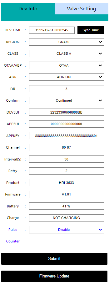
Dev-TimeEquipment time setting and calibrationREGIONLoRaWAN frequency bandCLASSLoRaWAN operation mode, Class A or Class COTAA/ABPLoRaWAN communication modeADRData rate adaptationDRData rate, can be adjusted when the ADR option is turned offCONFIRMUplink receipt confirmedDEVEUIAPPEUIAPPKEYOTAA node parameters, must be consistent across the serverChannelLoRaWAN channel, different channels should be separated by Spaces, such as "0-7 13 16-23"Interval(S)Period of transitionRetryLoRaWAN Class A, Class CProductProduct modelFirmwareFirmware versionBatteryBattery level (percentage)ChargeCharging statePulsePulse count on or offCounterPulse countSubmitClick Submit after the configuration is completeFirmware UpdateUsed for OTA firmware upgrade
ABP mode -- Most are the same as above, but the differences are listed below:
NWKSKEYAPPSKEYDEVADDRABP node parameters, must be consistent across the serverRX1 DELAY(S)Set the time for RX1 to be delayed onRX2 DR typeData rate, you can choose the default or set your ownRX2 DRCan be set when the DR type is customRX2 Freq typeRX2 Frequency band, you can choose the default or set your ownRX2 FreqCan be set when the Freq type is custom
The uplink port is fixed as port 2.
Valve Control Parameters
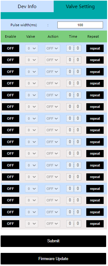
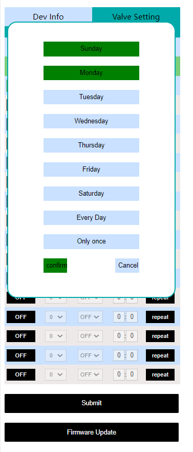
Pulse widthThe pulse time required to activate the controllerEnableRun a control optionValveValve number, one or two can be selectedActionThe valve controller performs the operation, opening or closingTimeSet the time to execute the controlRepeatExecute the control loop, which you can choose to do some few days or everyday a week or just once
After the configuration is completed, press the button Reset, The green light flashes once, indicating that the device enters the working mode. Cover the device.
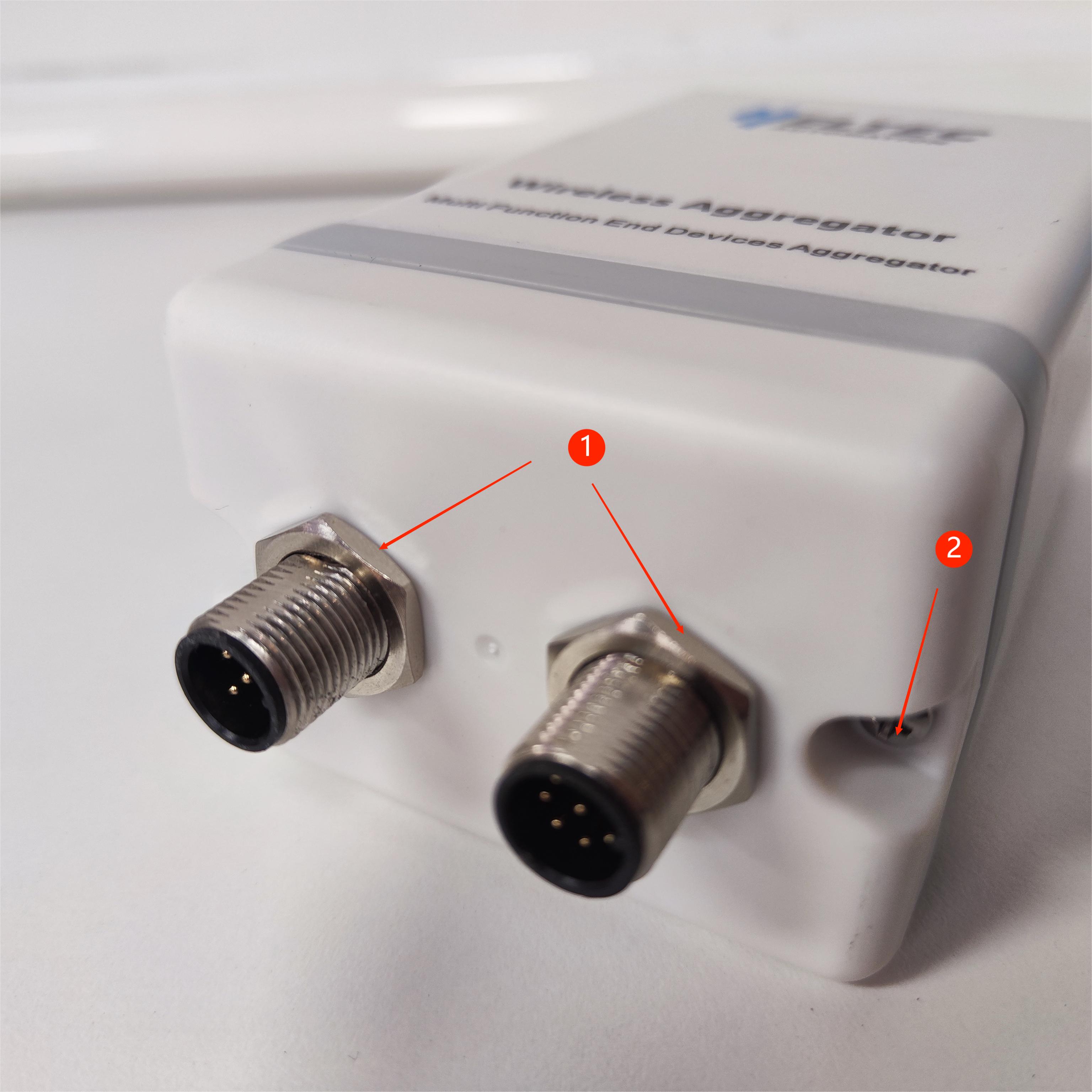
Connecting Valves
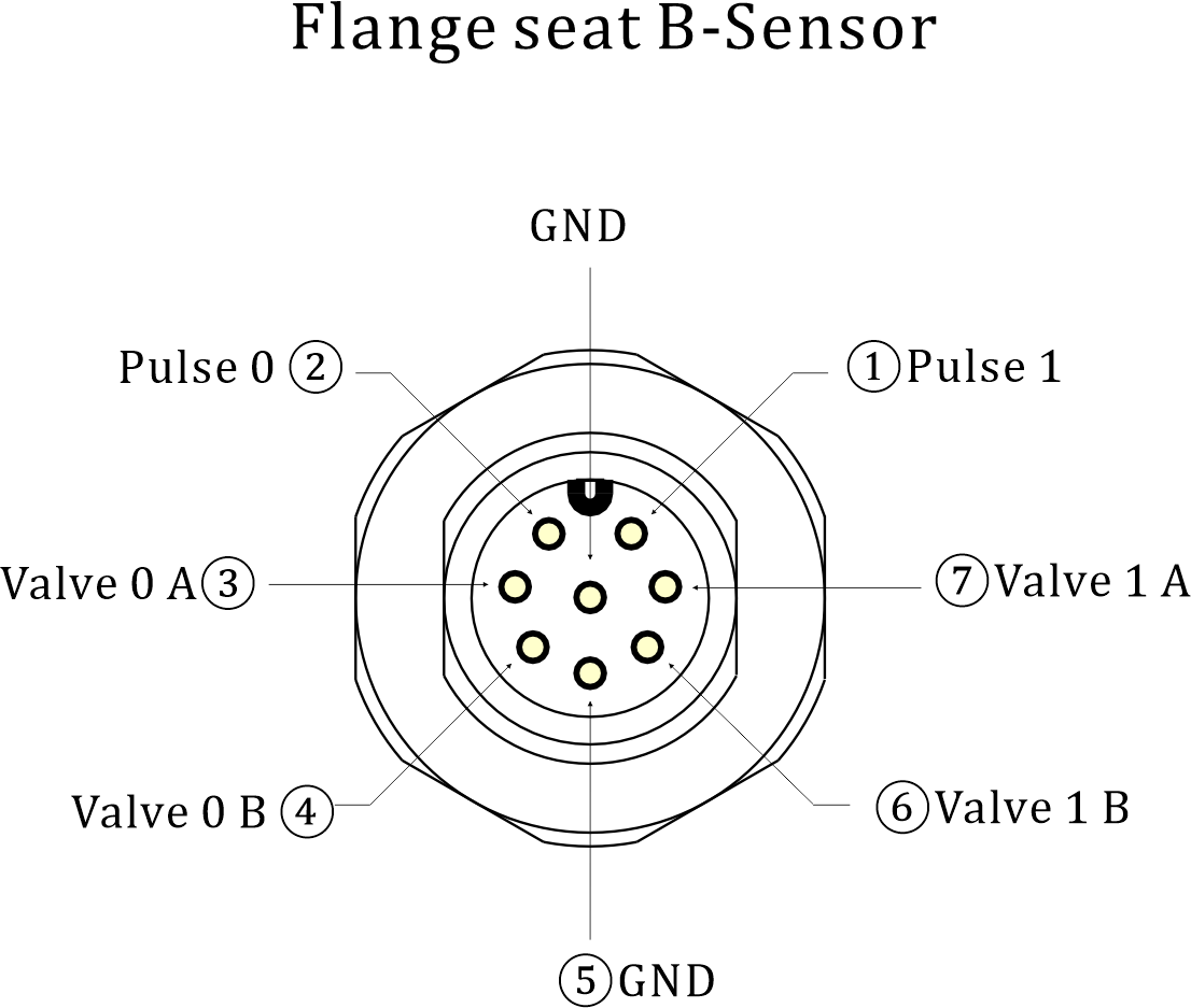
After the configuration is complete, connect the device with the valve. Connect the positive end of the valve to pin A and the negative end to pin B, there are two sets of pins '0' and '1' for use here.
To read an electrical Pulse, connect the positive electrode of the reading object to the Pulse pin and the negative electrode to the GND.
Note, please connect the adapter and valve cable first to avoid damage to the equipment.
If you need to use the HRI-3633 to power your valves and need a different version of firmware, you can get it from Heltec staff. At the same time, this version has only one set of valve control pins.
External Power Supply and Charging
HRI-3633 has integrated 4X2000mAh battery, and you can also use external DC power (7~24V), or solar panels to power the device, both of which can charge the device.
Note, please connect the adapter and valve cable first to avoid damage to the equipment.
You can refer to the pin definition below to connect the device.

Resources
Download Related Resources Wireless Aggregator series product application description