Usage Guide
Hardware Connection
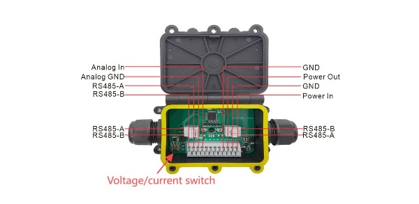
Power input and output
The voltage range is 4.5~50V, and the output is as much as the input.
RS485 to RS485
All RS485 interfaces are connected, you can freely choose one RS485 interface access, and choose another RS485 interface output.
4 ~ 20mA/1~5V to RS485
-
When you receive 4 ~ 20mA signal, you need to set the switch to "I"; when you receive 1~5V signal, then set the switch to "*** V***".
-
4 ~ 20mA/1 ~ 5V sensors are accessed from Analog_In and Analog_GND and output to Sensor_Hub/Wireless_ Aggregator from any RS485 interface.
Dataframe Description
Description
- Baud Rate: 9600
- Serial Port: 8N1
- Dataframe: 0x66(Slave address) 0x09(FUNC) 0x00 0x00(Begin address, 2Byte) 0x00 0x00 (Number of registers, 2byte) CRC16 (CRC Checksum 2Byte)
| Type | Address | Name | Quantity | Register Status | Resolution |
|---|---|---|---|---|---|
| INPUT REGISTER | 0x0000 | 4~20 mA | 2 | Read-only | 1 ua |
| INPUT REGISTER | 0x0002 | 1~5 V | 2 | Read-only | 1 mv |
- Negative: -1 == 0xFFFFFFFF; -2==0XFFFFFFFE;
Example
Reading voltage
- Send: 66 09 00 02 00 02 F5 DD
- Rec: 66 09 00 00 0E 0B 90 7B
0X00000E0B => 3595 mV
Reading current
- Send: 66 09 00 00 00 02 54 1D
- Rec: 66 09 00 00 17 70 DB C8
0X00001770 => 6000 uA
Actual error test
1~5V
| Input(mV) | Reading(mV) | Error value(mV) |
|---|---|---|
| 1000 | 998 | 2 |
| 2000 | 1996 | 4 |
| 3000 | 2995 | 5 |
| 4000 | 3992 | 8 |
| 5000 | 4988 | 12 |
4~20mA
| Input(uA) | Reading(uA) | Error value(uA) |
|---|---|---|
| 4000 | 4001 | 1 |
| 6000 | 5997 | 3 |
| 8000 | 7995 | 5 |
| 10000 | 9991 | 9 |
| 12000 | 12007 | 7 |
| 14000 | 14005 | 5 |
| 16000 | 16005 | 5 |
| 18000 | 18002 | 2 |
| 20000 | 19998 | 2 |