Usage Guide
*This document describes the Quick Start Guide for MeshSolar, You can refer to the instructional video for guidance: Instructional Video
Follow these steps EXACTLY to prevent board damage:
- Configure Battery Quantity
- Connect Batteries
- BMS Activation
- BMS Setup
Verify the battery switch alignment with the solder points and ensure the battery is connected before applying power (activation/charging/setup) to avoid board damage.
Battery Specifications
MeshSolar is available in two hardware versions, designed for Li-ion and LiFePO4 batteries respectively. Ensure you select the correct variant.
| Module | Frequency | Battery |
|---|---|---|
| HT-n5262S-I-LF | 470~510MHz | Li-ion |
| HT-n5262S-F-LF | 470~510MHz | LiFePO₄ |
| HT-n5262S-I-HF | 863~928MHz | Li-ion |
| HT-n5262S-F-HF | 863~928MHz | LiFePO₄ |
If you purchase this battery holder from Heltec, you'll need to buy flat-top batteries; otherwise, installation will be difficult.
Configure Battery Quantity
When configuring the battery quantity, disconnect both external power and batteries to prevent circuit board damage.
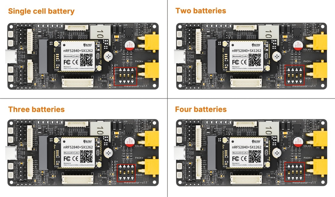
By default, MeshSolar support 4 series battery configuration. If you are using 1-3 batteries, you must properly short-circuit the unused battery circuits.
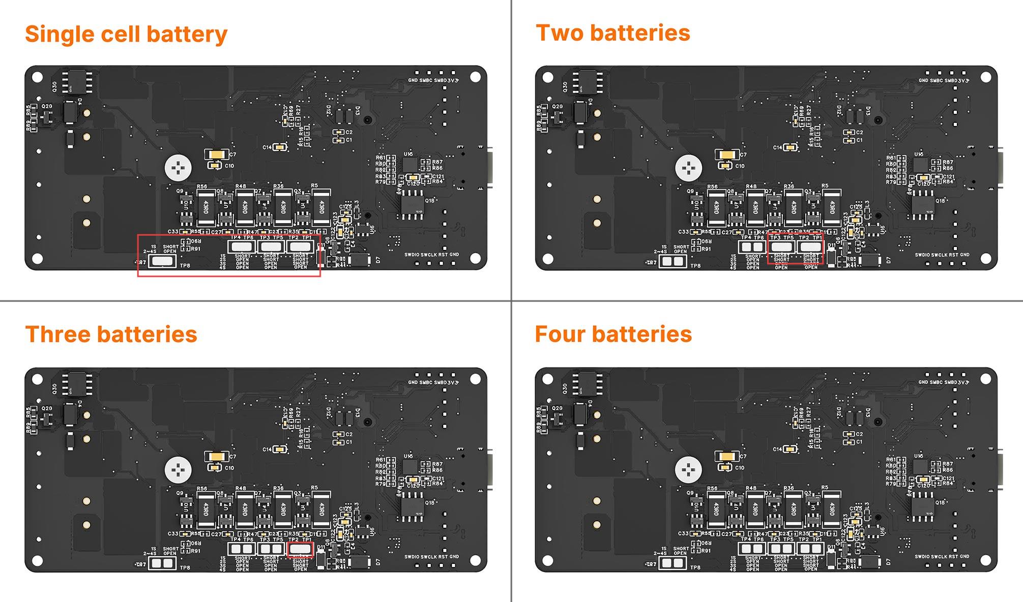
And only turn on the corresponding jumper switch.
The switches labeled 1/2/3/4 on the switch correspond to one/two/three/four battery cells, respectively. This means the switches represent the quantity of batteries, not their serial numbers. For example, in the factory default setting, if the battery quantity is set to FOUR, switch No.4 is turned ON, while switches No.1/2/3 remain OFF. When using THREE battery cells, turn OFF switches No.1/2/4, and turn ON switch No.3.
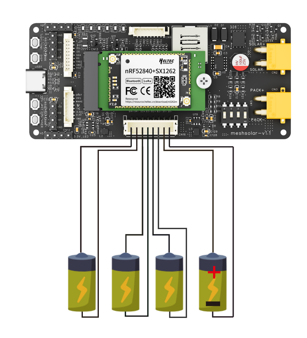
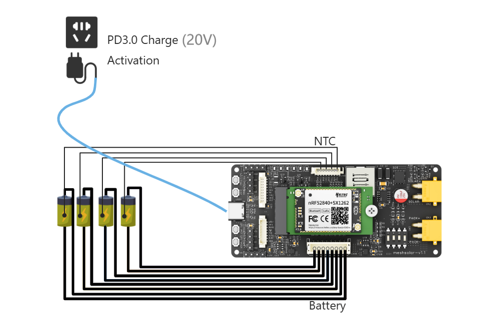
Battery Connection
The batteries will be connected in series inside the MeshSolar device. Do not perform external series/parallel connections. Simply connect each battery to its designated port. Ensure correct polarity alignment by referencing the polarity markings on the baseboard.
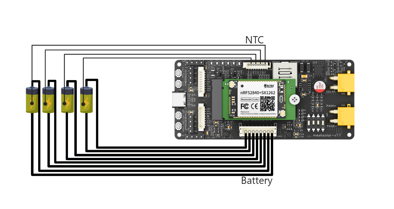
NTC Connection
Connect the NTC resistor, otherwise the device will enter low-temperature protection during reconfiguration.
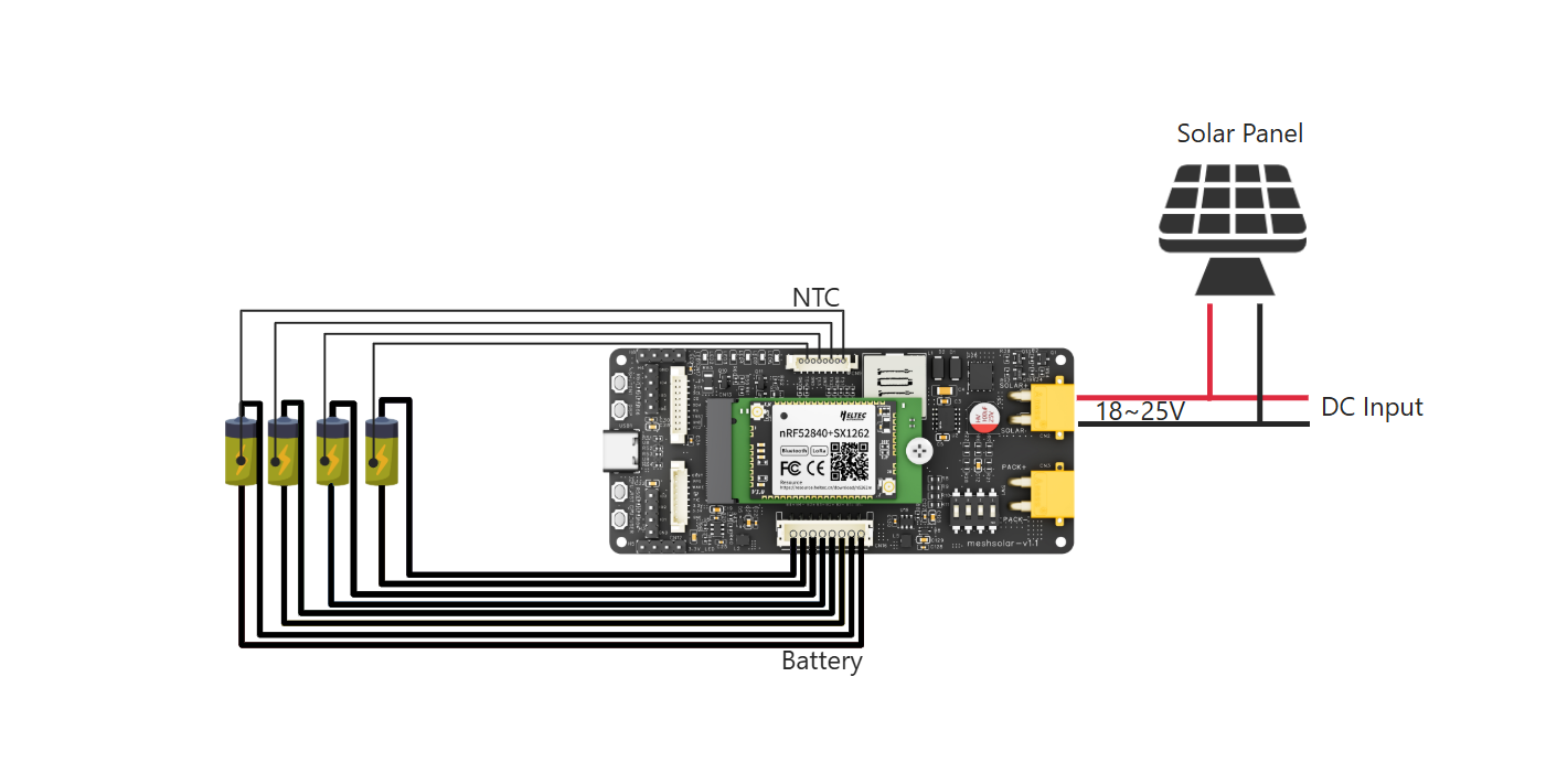
BMS Activation
When the device is used for the first time or shuts down due to battery removal/prolonged power failure, the BMS function must first be activated with an 18V-24V power supply before configuration can be performed or switched to battery power. The activation interface can be either:PD3.0(20V) input via USB-C port, or 18 ~24V Solar/DC input via the XT-30 connector. After successfully activated, the device's battery level indicator will illuminate.
After successful activation, Do Not Remove the Batteries, or the BMS chip requires reactivate.
BMS Setup
You can skip this step if using the default configuration, which is:
| Parameter | Default Value |
|---|---|
| Battery Type | Hardware-dependent |
| Number of Cells | 4 |
| Design Capacity | 3000mAh |
| Discharge Cut-off | 2.5V |
| Discharge High Temp Protection | 60℃ |
| Discharge Low Temp Protection | 0℃ |
| Charge High Temp Protection | 45℃ |
| Charge Low Temp Protection | 0℃ |
| Temperature Protection | On |
- Ensure the following:
- The main control module is properly connected
- The battery soldering points and switch configuration are correct
- The BMS function has been activated
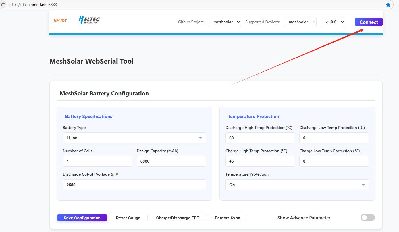
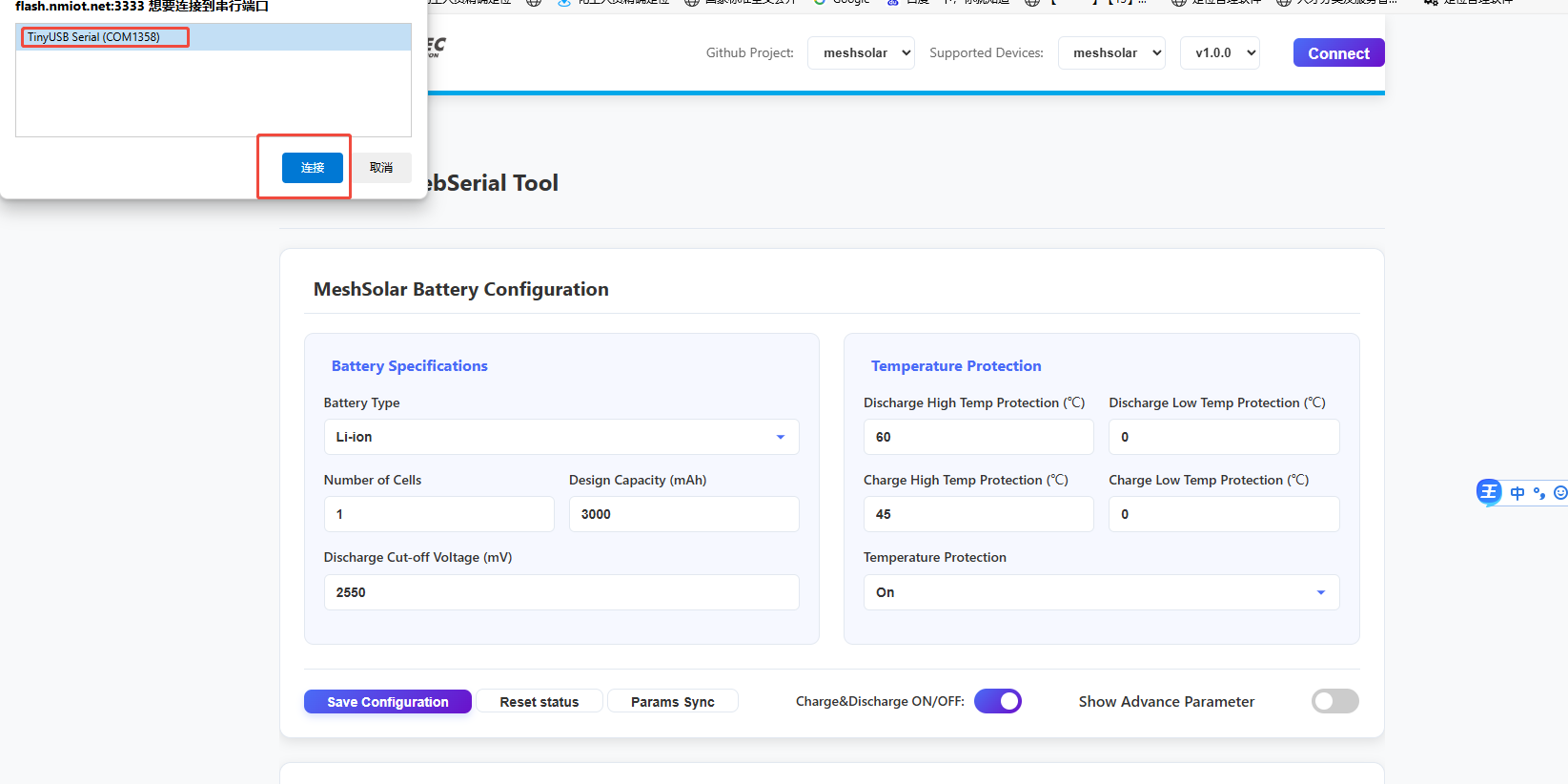
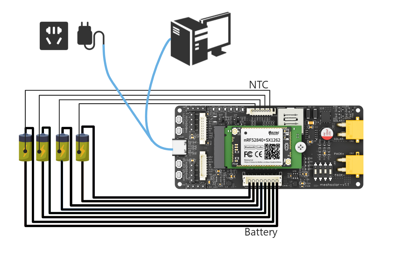
- Connect devices and PC via USB-C cable, open the Configuration Page in your browser, click the
Connectto choose the port.
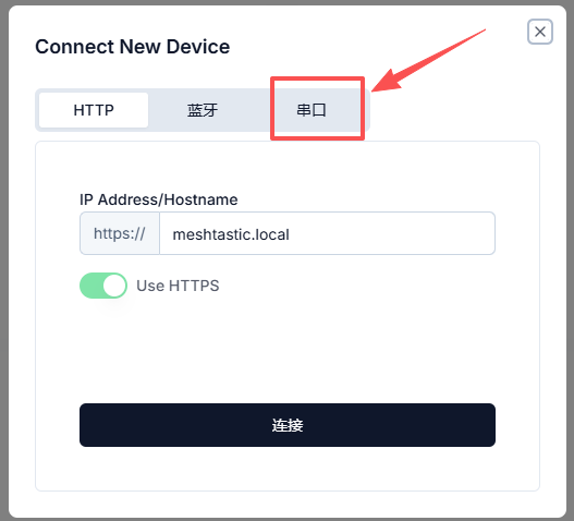
If you are using Meshtastic firmware, you need to enable the device serial port function
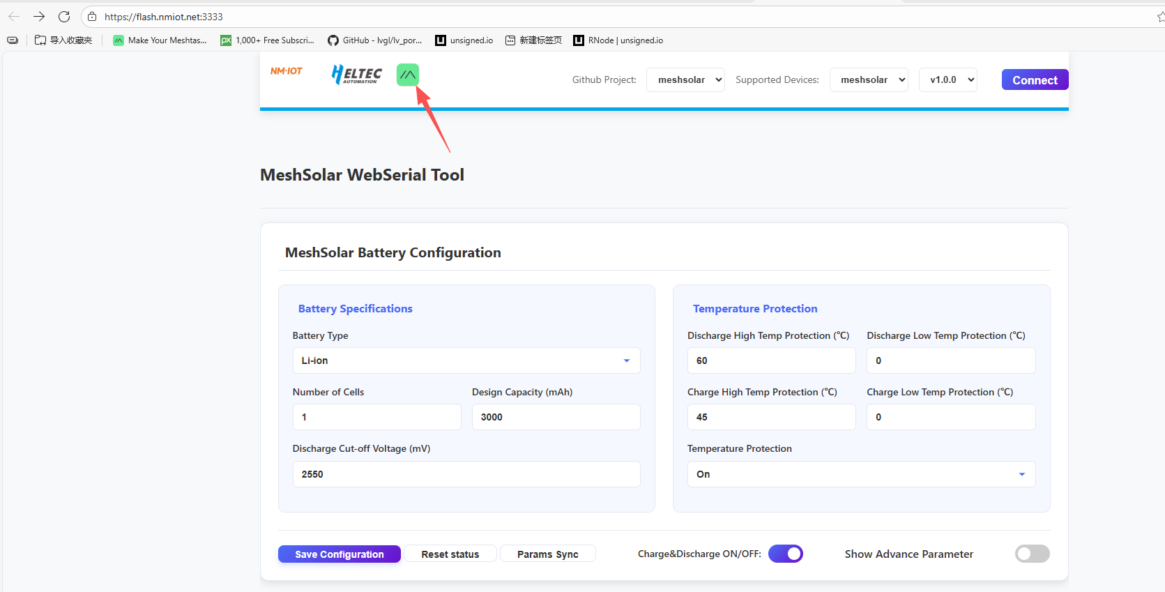
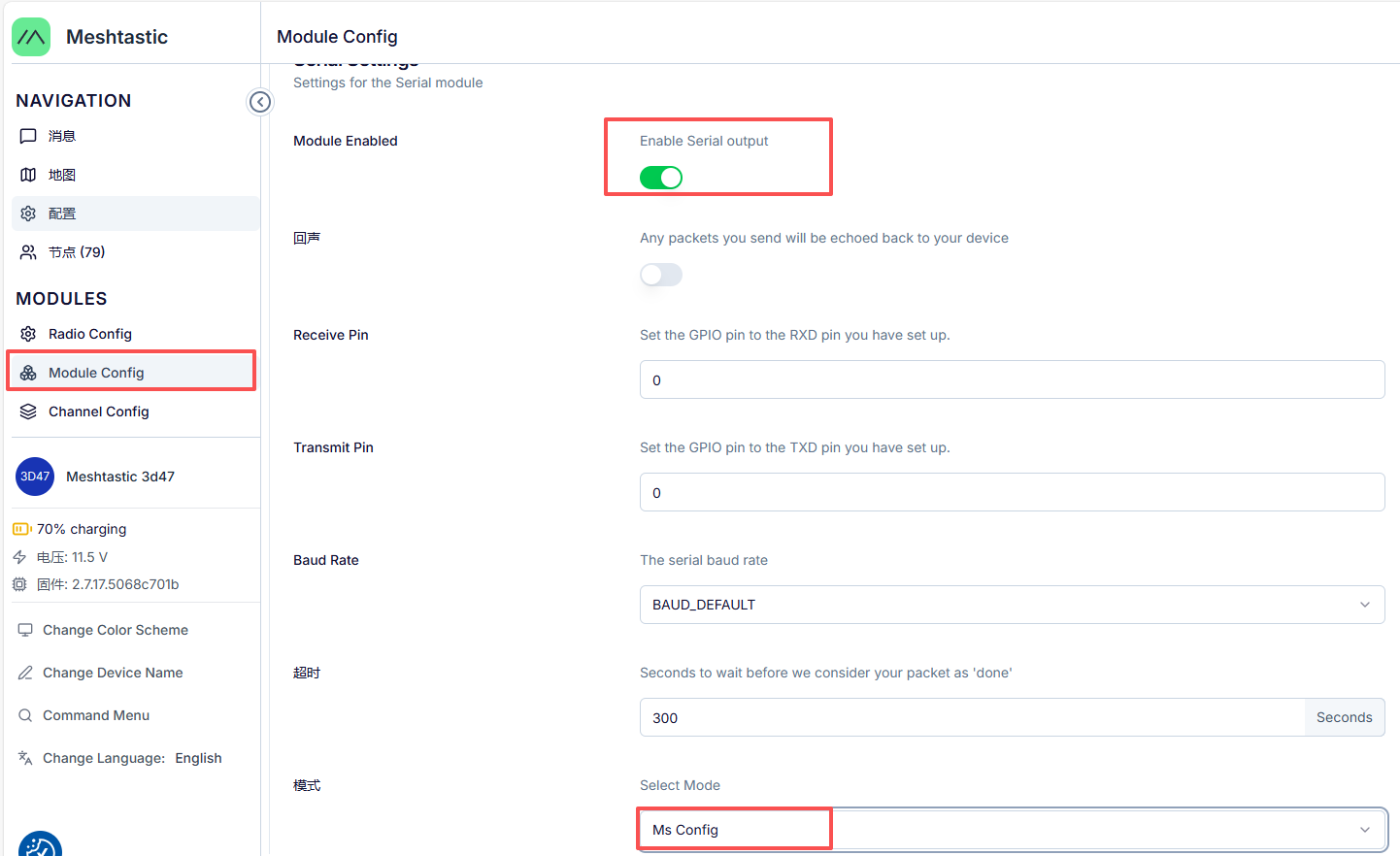
Once the device is successfully connected, verify that the module’s serial output is enabled and the operating mode is configured as MS Config Mode.
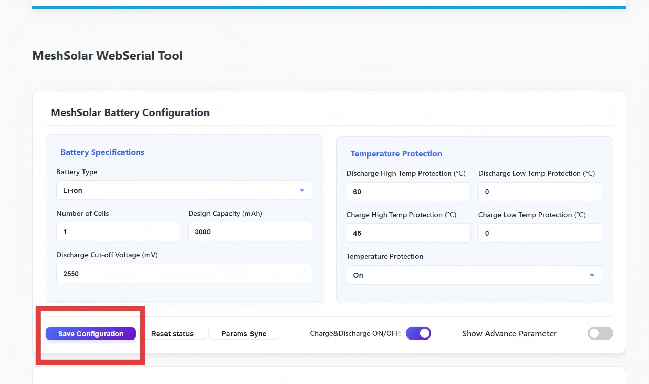
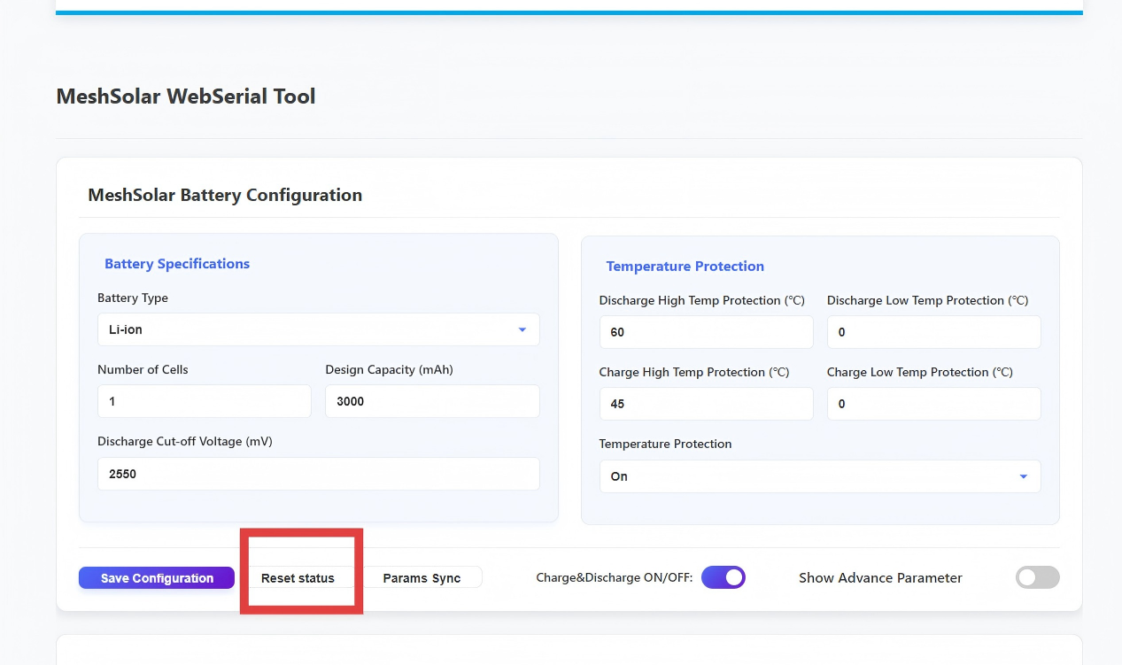
- Configure based on your battery requirements (cell count, capacity, etc.), then click Save Configuration to apply.
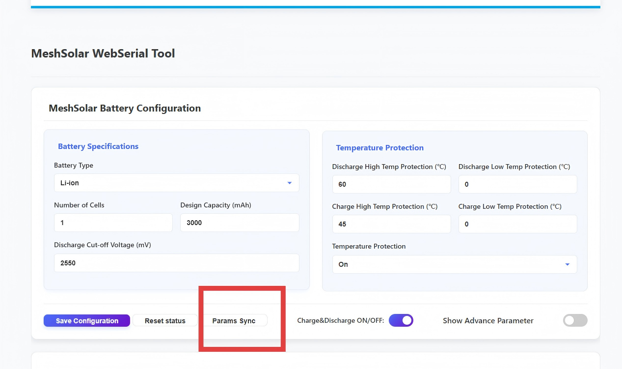
- If you forget the original settings during configuration, click Params Sync to synchronize current system parameters. Note: The system will automatically sync once when the serial port is connected.
- After completing all configurations, click Reset Status to finalize.
DC & Solar Panel Wiring
-
Voltage: 18-25V
-
Connector: XT30 female socket (inner pin type)
USB-C Input
-
When PD3.0 is detected: The USB-C port charges the battery and powers the main control module when PD3.0 protocol is identified.
-
No protocol detected: Without protocol recognition, the USB-C port only supplies power to the main control module
Pack Output/Input
Connector: XT30 female socket (inner pin type)
Output
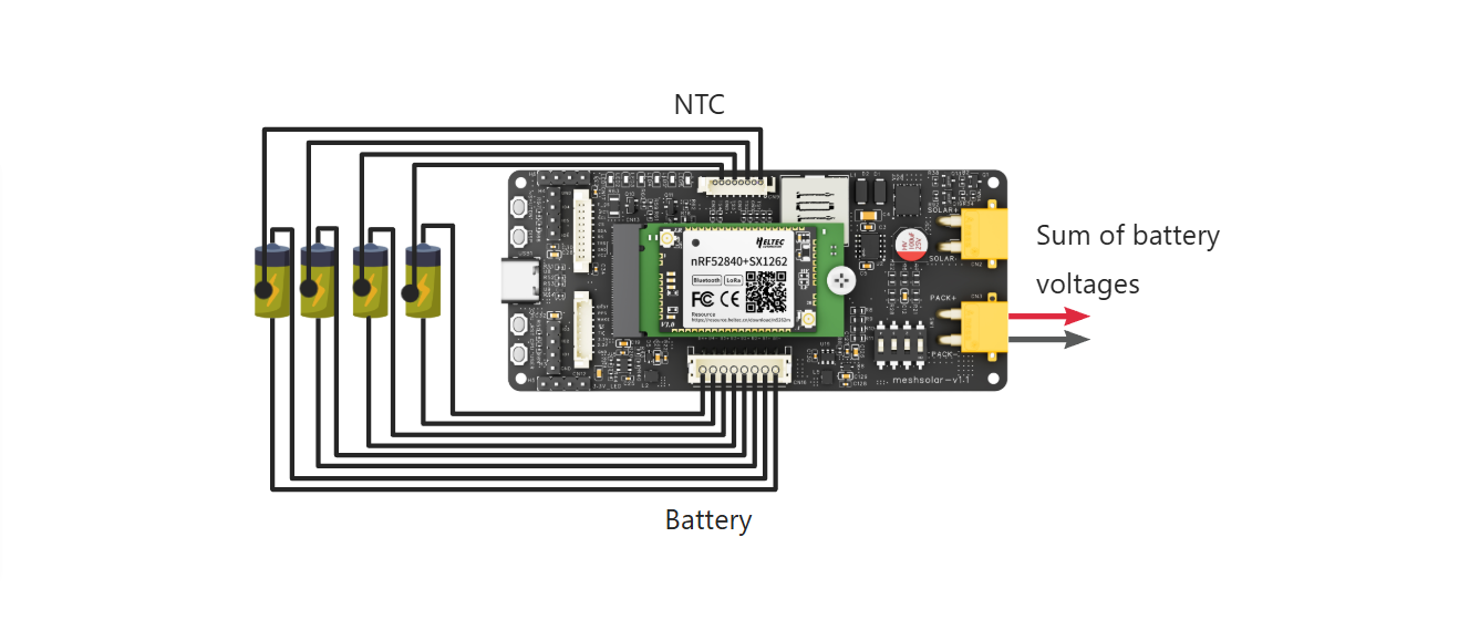
Voltage: Sum of battery voltages
Input(Not Recommended)
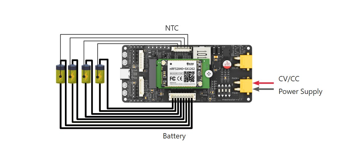
When the Pack interface is used as input:
- A constant voltage/constant current (CV/CC) power supply must be used; ordinary chargers are not suitable.
- The power supply voltage depends on the battery type and quantity. Generally, it should be:
- Lithium batteries: 4.2V × number of cells
- LiFePO4 batteries: 3.6V × number of cells
- The current must not exceed the overcurrent protection limit.
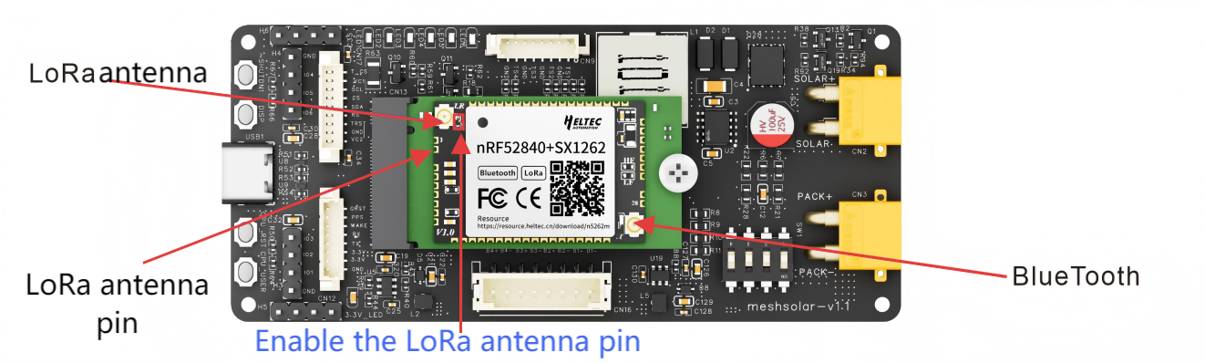
Antenna Connection
- The LoRa and Bluetooth antennas are located on the central control module of the device, with IPEX1.0 (UF.L) connector specifications.
- f using IO pins to connect the antenna, please bridge the solder pads in the red box area shown in the figure below.
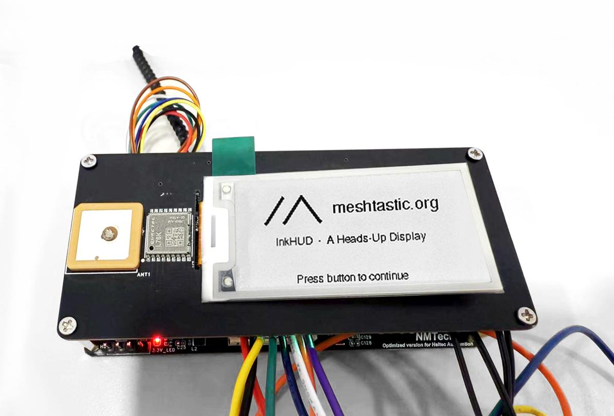
Display
MeshSolar has opened an MX1.25-9Pin display interface complete with connecting cables. Heltec offers an expansion board with display and GPS functionality, providing multiple screen options including: 0.96-inch OLED, 1.90-inch TFT, or 2.13-inch E-Ink. Meshsolar expansion board
GNSS Module
MeshSolar has opened an MX1.25-8Pin GNSS interface complete with connecting cables.
- This interface is fully compatible with the L76K GNSS module.
- Additionally, Heltec provides a display and GPS expansion board that integrates the L76K GPS module while offering multiple screen options.
Firmware Upload
Via DFU Mode:
- Connect the device to your computer using USB-C.
- Double-press the RST button to enter DFU mode.
- A removable drive named HT-N5262 will appear on your computer.
- Paste your firmware file into this drive.
Meshtastic Serial
Enabling the Meshtastic serial function allows you to modify relevant parameters directly in the BMS tool while running Meshtastic firmware, without needing to reinstall dedicated BMS firmware.
- Users can download the official Meshtastic firmware from GitHub, select the nrf52840 package and extract it, then choose the Meshsolar version inside the package for installation.
- After downloading the firmware, connect it to the Meshtastic App. For detailed instructions, please refer to the official documentation.
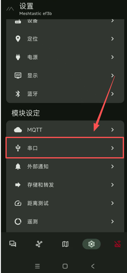
- After successfully connecting to the Meshtastic App, go to the settings and adjust the serial port configuration.
- Click on the
serial portin the settings
- Select
Enable
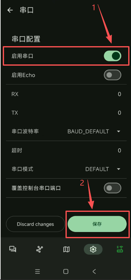
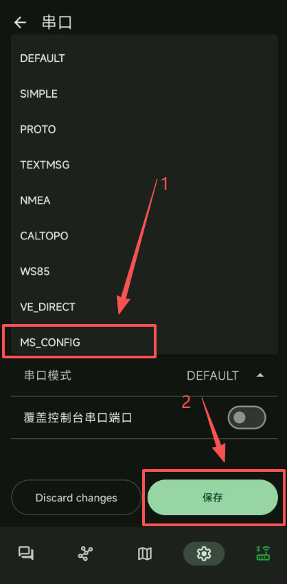
- Click the mode, then select
MS_CONFIGunder the serial port mode and save the settings. If you don't see this option, please update your app.
Technical Support Email: support@heltec.cn