- ESP32 Series Quick Start
- LoRaWAN
- Meshtastic
Heltec ESP32 Series Quick Start
This article describes the installation of the Heltec ESP32 series development framework and library.
Summary
Heltec's Arduino-based ESP32 development environment consists of two parts:
-
Heltec ESP32 Development Framework: Fully adapted from the official Espressif library, it includes board definitions, core functionalities, and examples for the ESP32 (such as Wi-Fi, Bluetooth, and external drivers etc.).
-
Heltec Extended Example Library: This library depends on the aforementioned ESP32 Development Framework**. It includes examples for LoRa/LoRaWAN, display demonstrations, GPS, sensors, and factory test programs for Heltec products etc..
Framework v3.0.0 and Library v2.0.0 are updated together, Older frameworks and libraries are no longer applicable to the new ones.
You can also use the official Espressif Arduino framework as a replacement for the Heltec ESP32 Development Framework. Just ensure that the corresponding version is compatible.
Preparation
Hardware
- Heltec ESP32 Series Node
- High quality USB_Type_C cable
Some cables only charge and do not transfer data, so you need to avoid this when uploading code.
Software
- USB driver: CP210x Driver.
- Arduino IDE.
- GIT
ESP32 Dev Environment Installation Tutorial For Beginners
There are three methods to install the development framework, choose one of they:
- Arduino IDE
- Git
- Local Files
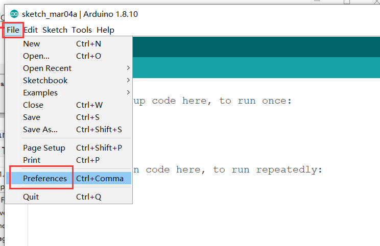
- Open Arduino IDE, and click
File->Peferences.
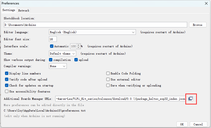
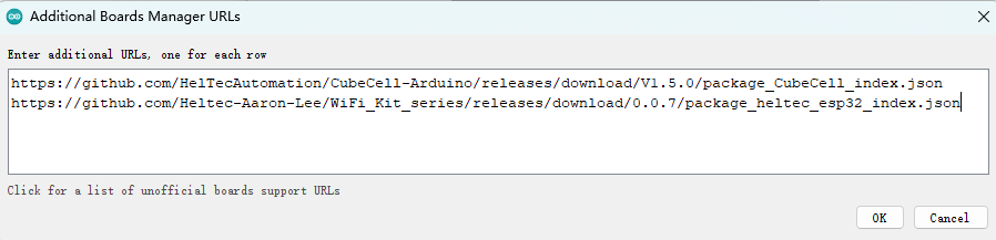
- Input the last ESP32 package URL: https://resource.heltec.cn/download/package_heltec_esp32_index.json
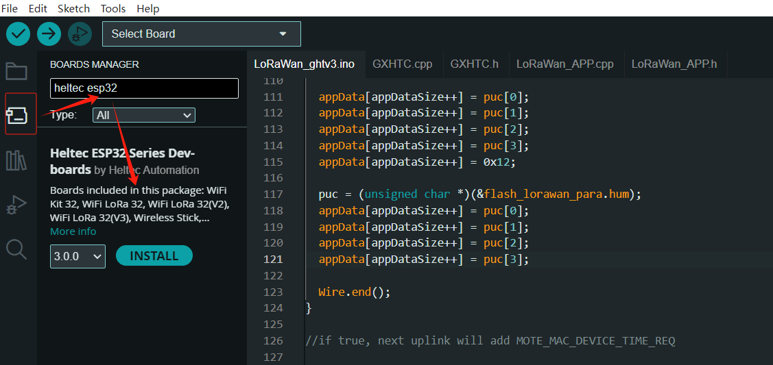
- Click on the
Boards Managericon on the left side, and enter "heltec esp32" in the search box that pops up, then select the latest version and clickINSTALL.
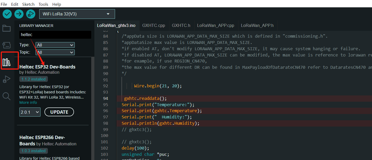
- Install Heltec Esp32 Extended library
Click on theLibrary Managericon on the left side, search for "HELTEC ESP32", select the latest version and install
It is recommended to follow the path and file name as described below as much as possible to avoid unnecessary trouble.
Install Heltec ESP32 Development Framework
Check the following links for your operating system, the specific operation steps are detailed in the link:
- For Windows
- For MacOS
- For Linux
After installation, please execute "get.exe" under the path of "Arduino\hardware\heltec\esp32\tools" to obtain the latest compilation tool.
Install Heltec Extended Example Library
The above is the framework installation. If you need to install the Heltec ESP32 extended library, you can refer to this link:
Follow the instructions in the Readme.MD to install.
It is recommended to follow the path and file name as described below as much as possible to avoid unnecessary trouble.
-
Download the development environment. Download Framework
-
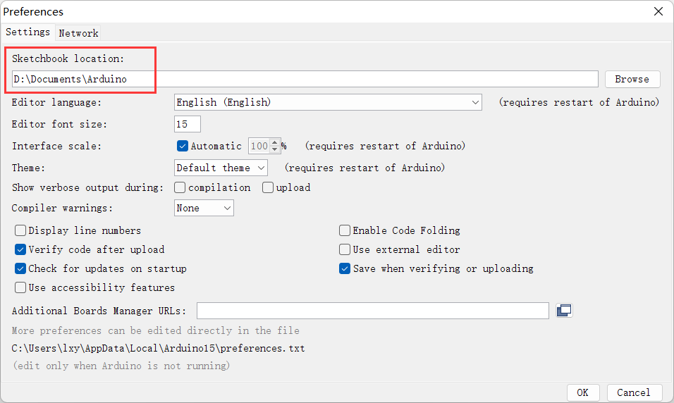
Open Arduino IDE, and click
File->Peferences.
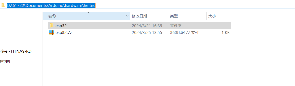
- Go to the folder in the red box.
- Create a new "hardware" folder in the Arduino folder. If there is already a "hardware" folder, you don't need to create a new one.
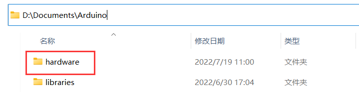
- Creat a new "heltec" folder in "hardware" folder.
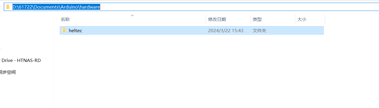
- Go to the "heltec" folder and extract "esp32" into this folder.
- Go to the "heltec" folder, refer to the figure below to confirm whether the path in the red box is correct.
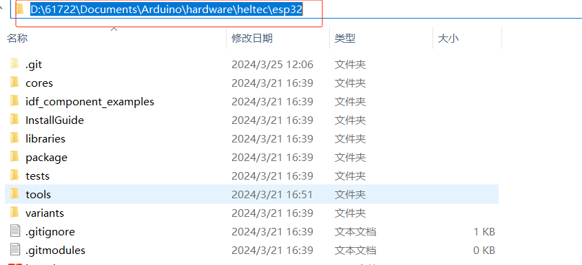
- Restart the Arduino IDE to confirm whether the development environment is installed successfully.
- For special code library, search for "HELTEC ESP32" in
Library Manager, select the latest version and install:ESP32 Series Library
Programming
Once you have the framework and libraries installed, connect your computer to the board and start programming nodes.
Example
-
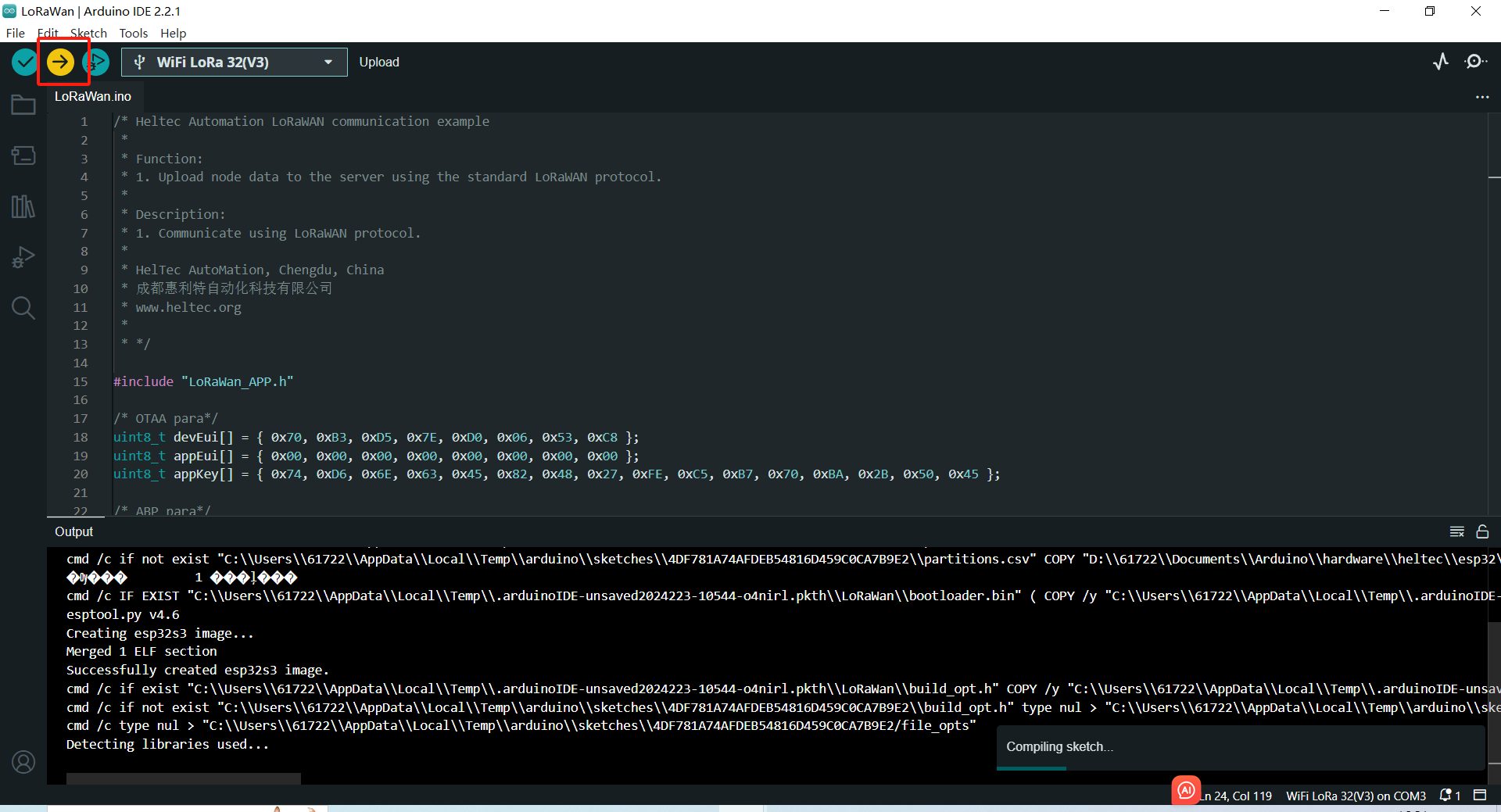
Connect your node to the computer with a USB cable.
-
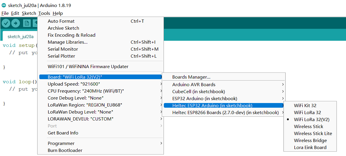
Open Arduino IDE, Correctly select a board and relevant options in the
Toolsmenu:
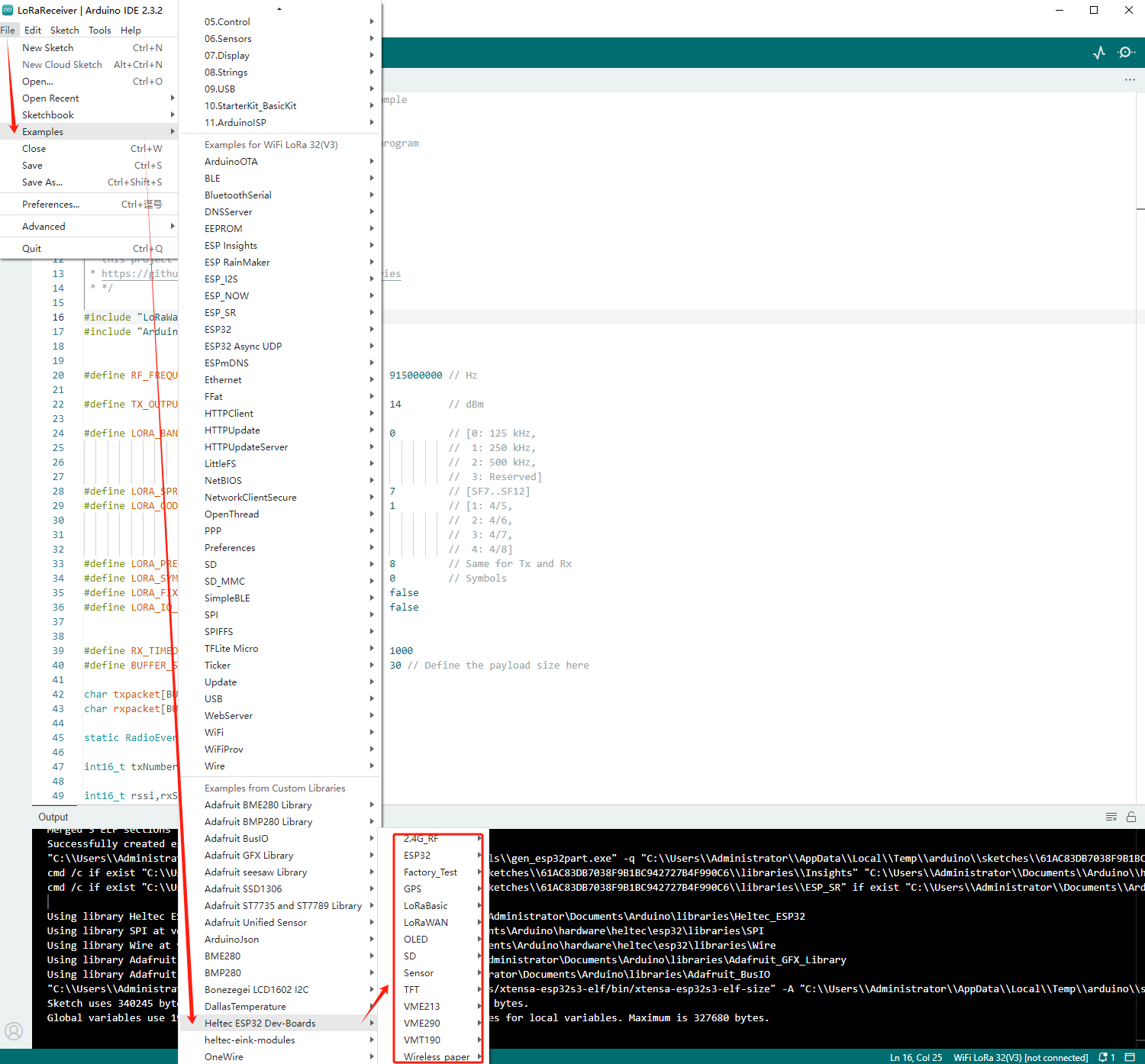
- Then select an example.
- To execute the code in a library, you need to mouse over, scroll down, find the library, and find the code in it.
- Compile & Upload
If you cannot upload the code, please manually enter the BOOTLOADER mode: hold down the PRG (USER/BOOT) key and do not release it, press the RST key once, and then release the PRG (USER/BOOT).
New program
Open Arduino IDE, create a new .ino file, then copy the below code.
#include <heltec.h>

// the setup routine runs once when starts up
void setup(){

  // Initialize the Heltec ESP32 object
  Heltec.begin(true /*DisplayEnable Enable*/, true /*LoRa Disable*/, true /*Serial Enable*/, true /*PABOOST Enable*/, 470E6 /**/);
}

// the loop routine runs over and over again forever
void loop() {

}
compile it and upload, the screen (if this board has a screen) will show and Arduino's serial monitor will print something, it means Heltec ESP32 board is running successfully!
LoRaWAN Getting Start
This article is intended to describe how to use the Heltec ESP32 LoRaWAN library.
This library is make LoRaWAN 1.0.2 protocol running with ESP32 Arduino. Only support the ESP32 + LoRa series products made by HelTec Automation(TM), and a LoRa gateway is must needed.
Heltec ESP32 LoRaWAN library need a license to active, it's relative to ESP32's Chip ID. Query your board's license here: http://resource.heltec.cn/search.
- LoRaWAN Configuration Parameter
- Connect to LoRaWAN server
Preparation
- Install Arduino IDE. How to install please click here.
- Install Heltec ESP32 series Arduino development framework. Installation manual please refer to here.
- Install Heltec_ESP32 Library.
- An ESP32 + LoRa node.
- High quality USB cable.
Configure Parameters
-
Connect the development board to the computer through USB data cable.
-
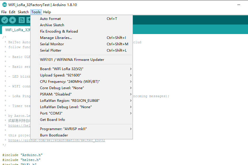
Open the Arduino and in the
Toolsoption, select the appropriateBoard,Port.
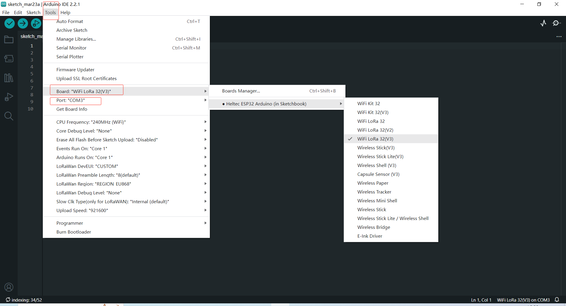
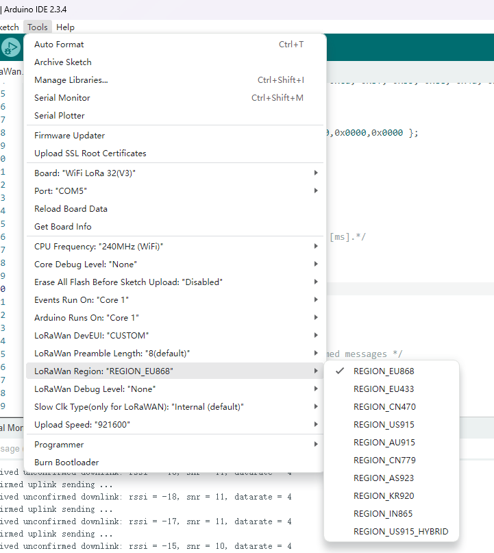
- In
Toolsoption,Board,Upload Speed,CPU Frequency,Core Debug Level,PSRAMare ESP32 chip's normal option, just keep default. Special notice theLoRaWan Region,LoRaWan Debug Level,LoRaWANDEVEUI.
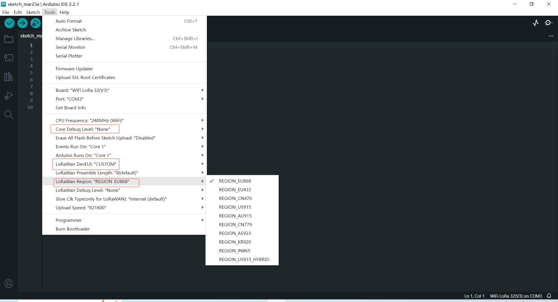
- LoRaWan Region -- LoRaWAN protocol region definition, strictly follow LoRaWAN™ 1.0.2 Regional Parameters rB;
- LoRaWan Debug Level -- Messages printed via serial.
- None -- Default;
- Freq -- Uplink/downlink frequency;
- Freq && DIO -- Uplink/downlink frequency and DIO interrupt information;
- Freq && DIO && PW -- Uplink/downlink frequency, DIO interrupt information and low power status.
- LORAWAN_DEVEUI -- LoRaWAN Device EUI generate method
- CUSTOM -- Defined by the user in the DevEui array of the code, 8 bytes;
- Generate By ChipID -- Generated according to the Chip ID of the chip. Selecting this option will override the setting in the DevEui array in the code.
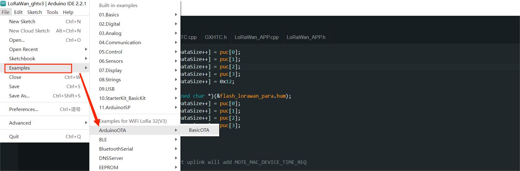
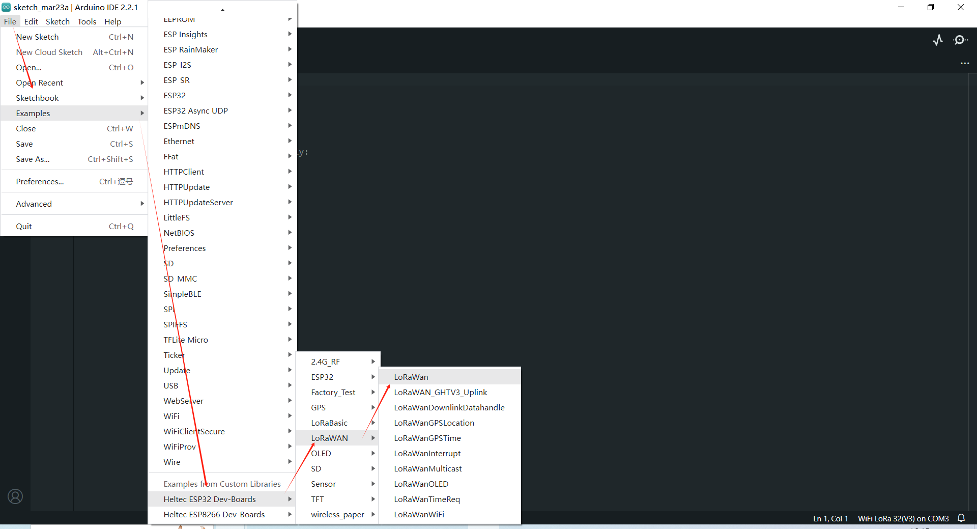
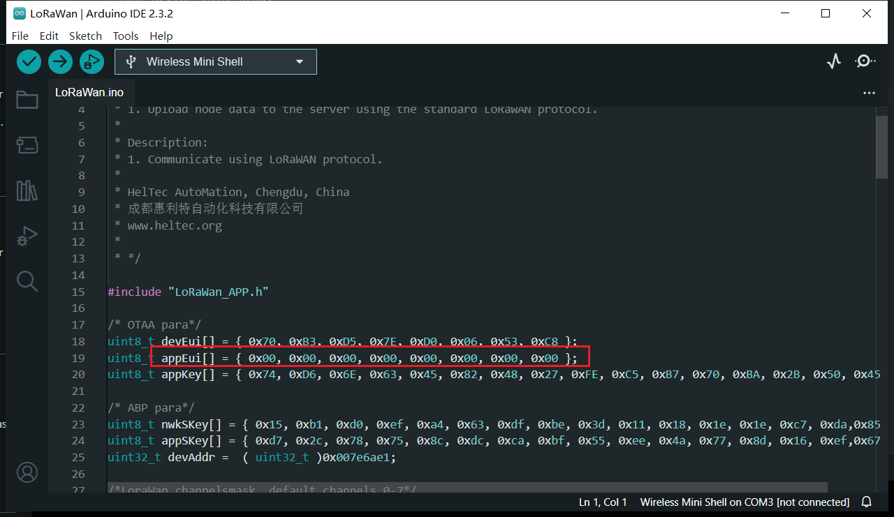
- Follow the path shown below to open the LoraWAN demo code.
- Fill in DevEu AppEui AppKey in the following figure in the red box in the example format, which will be used in the website registration.
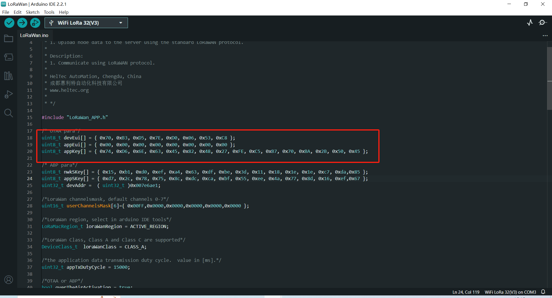
- DevEui -- Mote device IEEE EUI (big endian), 8 bytes;
- AppEui -- Application IEEE EUI (big endian), 8 bytes;
- AppKey -- AES encryption/decryption cipher application key, 16 bytes;
This example uses the OTAA pattern as an example, and for the differences in the ABP pattern, please refer to this link: ABP mode
- Effective load is here.
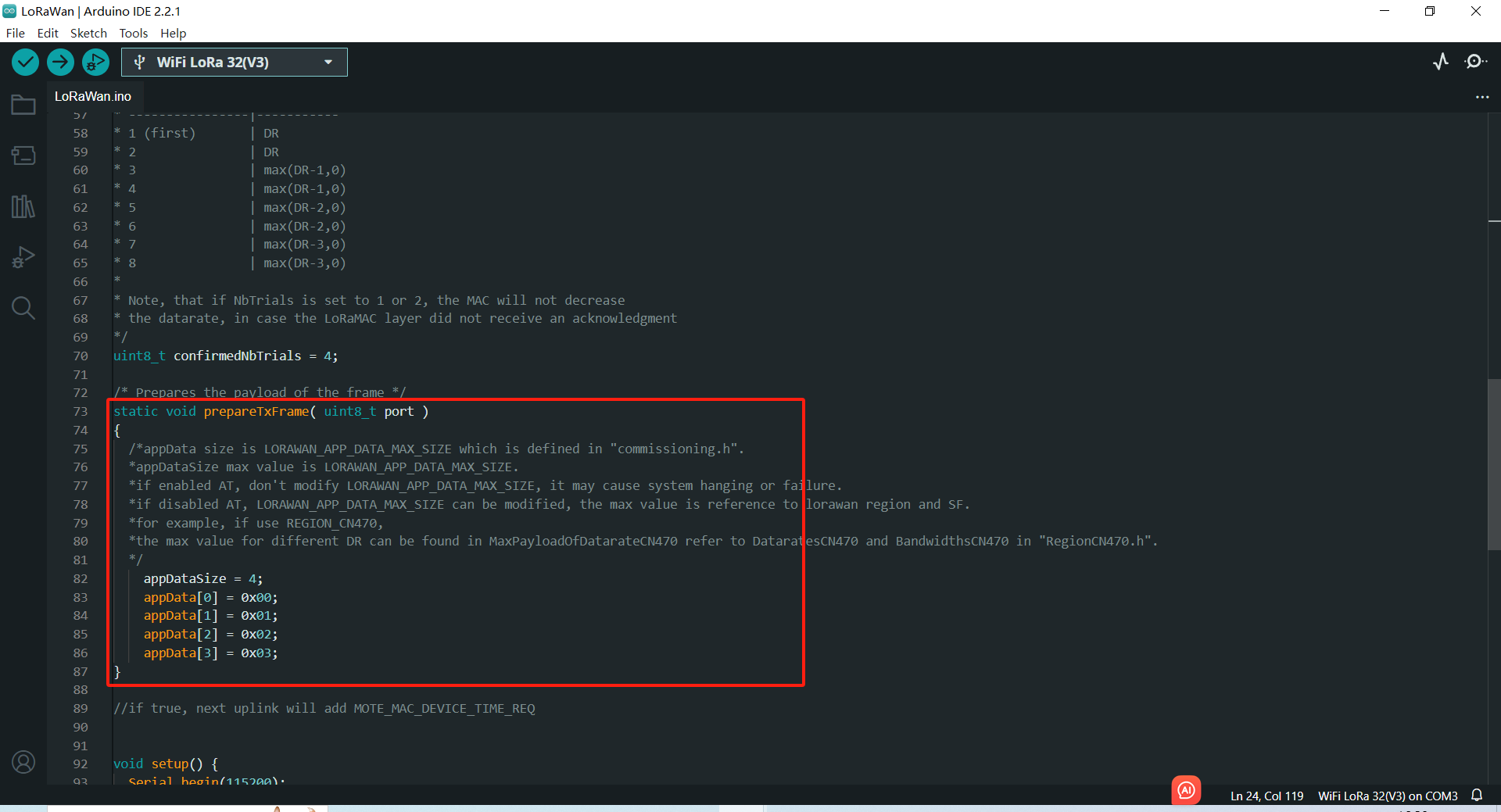
Print too much messages may cause the system unstable.
-
Other relevant parameters are in the
.inofile, You can come back to it after you know lorawan well. -
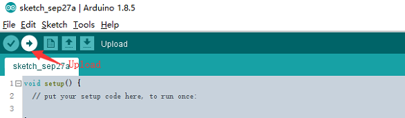
Click
Uploadto upload the code.
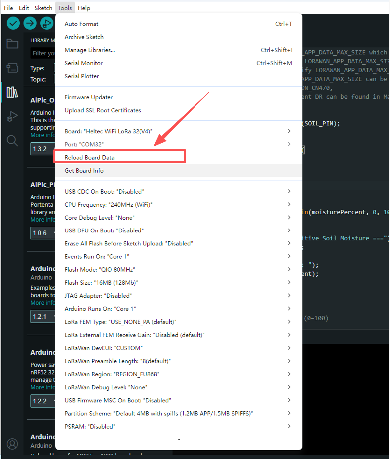
It is recommended to refresh the cache after updating libraries in Arduino, so the changes can take effect immediately.
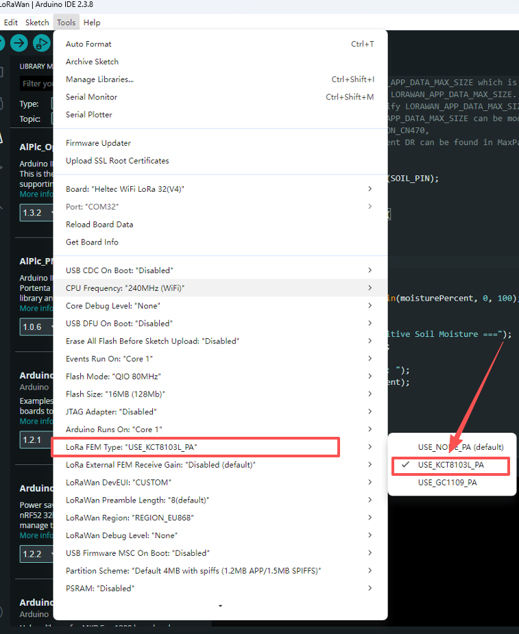
For the WiFi LoRa 32 V4 development board, different hardware revisions require selecting the correct LoRa FEM option in the Tools menu.
- V4.2, select
USE_GC1109_PA. - V4.3, select
USE_KCT8103L_PA.
Preparation
- A ESP32 + LoRa node that's configured and uploaded code, as described in the previous topic: ESP32 + LoRa” Node Preparation & Config Parameters
- A LoRa server, We recommend the following three:
- A Gateway that matches the LoRaWAN region of the node, and already is connected to the lora server. If you are using Heltec Gateway, you can find out how to connect to the server in the Heltec Gateway documentation
Important to know
Regardless of which LoRaWAN NS, the parameters that need to be configured are similar. Ensuring that the relevant configurations of NS and Node are consistent is the key to ensuring successful LoRaWAN communication.
Device Type
Generally, you will be asked to select a LoRa Gateway or LoRa Node.
LoRaWAN Class
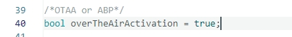
OTAA or ABP, choose one of the while working, keep LoRa Node and NS select the same LoRaWAN Class.
For development devices with source code, you may see something like this:
Region
LoRaWAN protocol agreement RF communication parameters. For technical details, please refer to LoRaWAN™ 1.0.2 Regional Parameters and LoRaWAN Frequency Plans and Regulations by Country/Region can make sense to you.
The region setting of LoRa Node, LoRa Gateway, LoRaWAN NS should be strictly the same.
For development devices with source code, you may see something like this:
OTAA Parameter
For OTAA LoRaWAN Class, mainly includeDevEUI, AppEUI (Also called JoinEUI), AppKey, the LoRa Node and NS should strictly keep the same.

If you select ABP, you do not need to set OTAA parameters.
ABP Parameter
For ABP LoRaWAN Class, mainly include NetworkSecuritykey, ApplicationSecuritykey, DeviceAddress, the LoRa Node and NS should strictly keep the same.
For development devices with source code, you may see something like this:

If you select ABP, you do not need to set OTAA parameters.
Connect to LoRaWAN Server
Before that, make sure there is a LoRa Gateway active in your server.
- Connect to SnapEmu
- Connect to TTN/TTS
- Connect to ChirpStack
Manual registration on SnapEmu
Log-in to SnapEmu by using their Heltec website account. Access into the devices page to register new device.
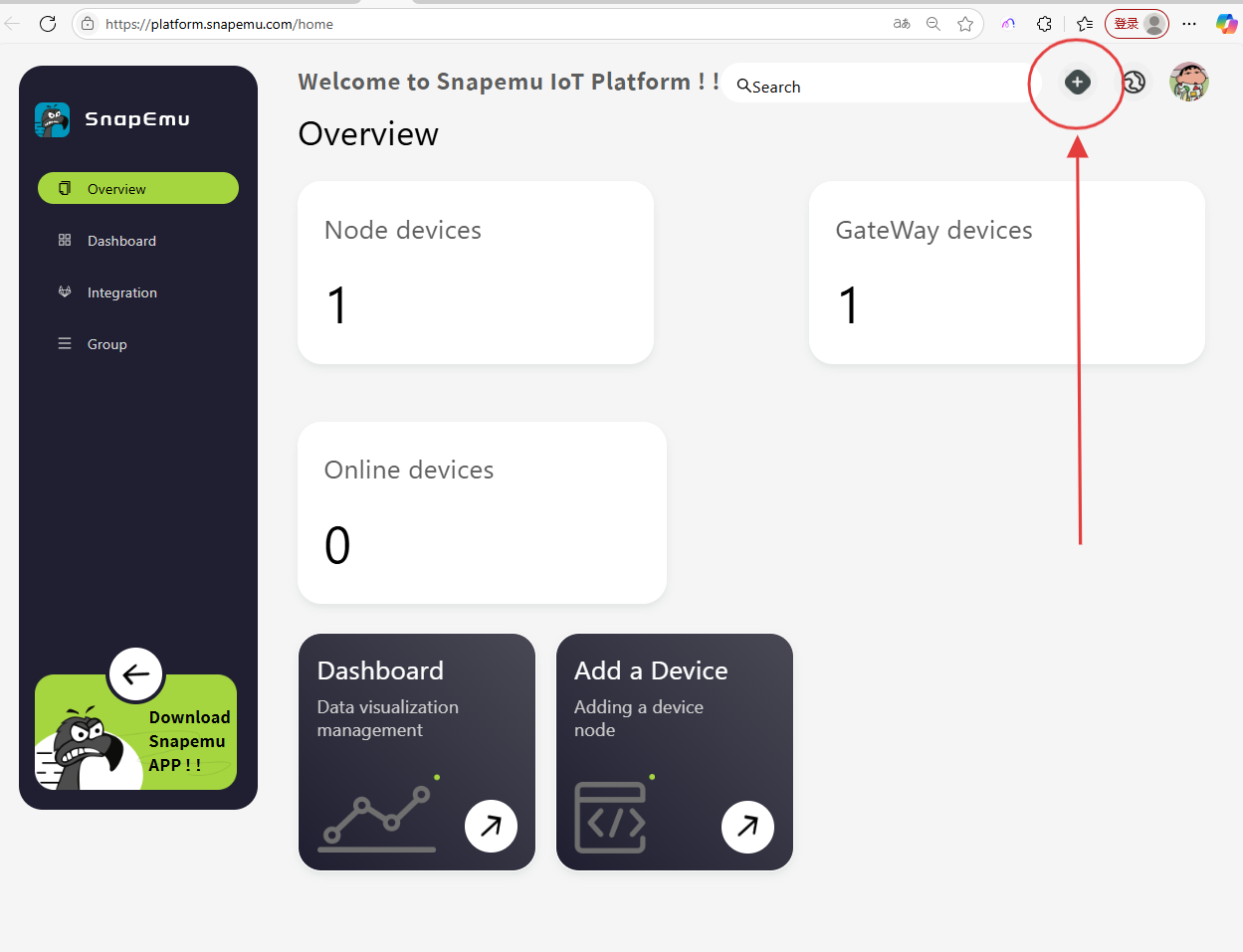
Click + and file in relevant device information.
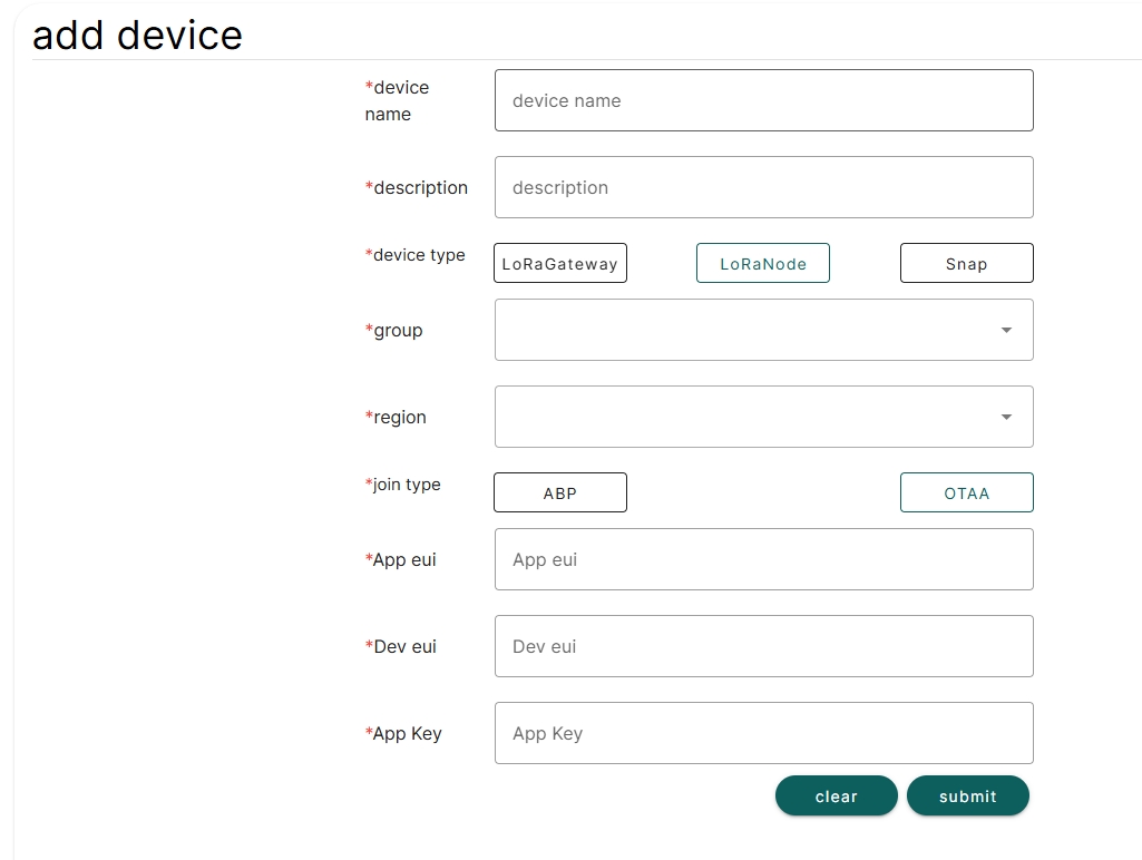
In the Add device step, file in the LoRa Node parameters and double check to make sure the content are the same with each other. If everything goes well, LoRa Node is successfully registered after Submit.
TTN/TTS is not Heltec's business, we cannot provide technical support for this platform, please refer to the official documentation of TTN/TTS.
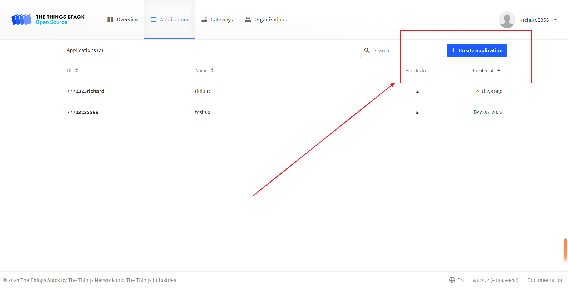
- Log in to the TTS server web page, register a new “Applications” .
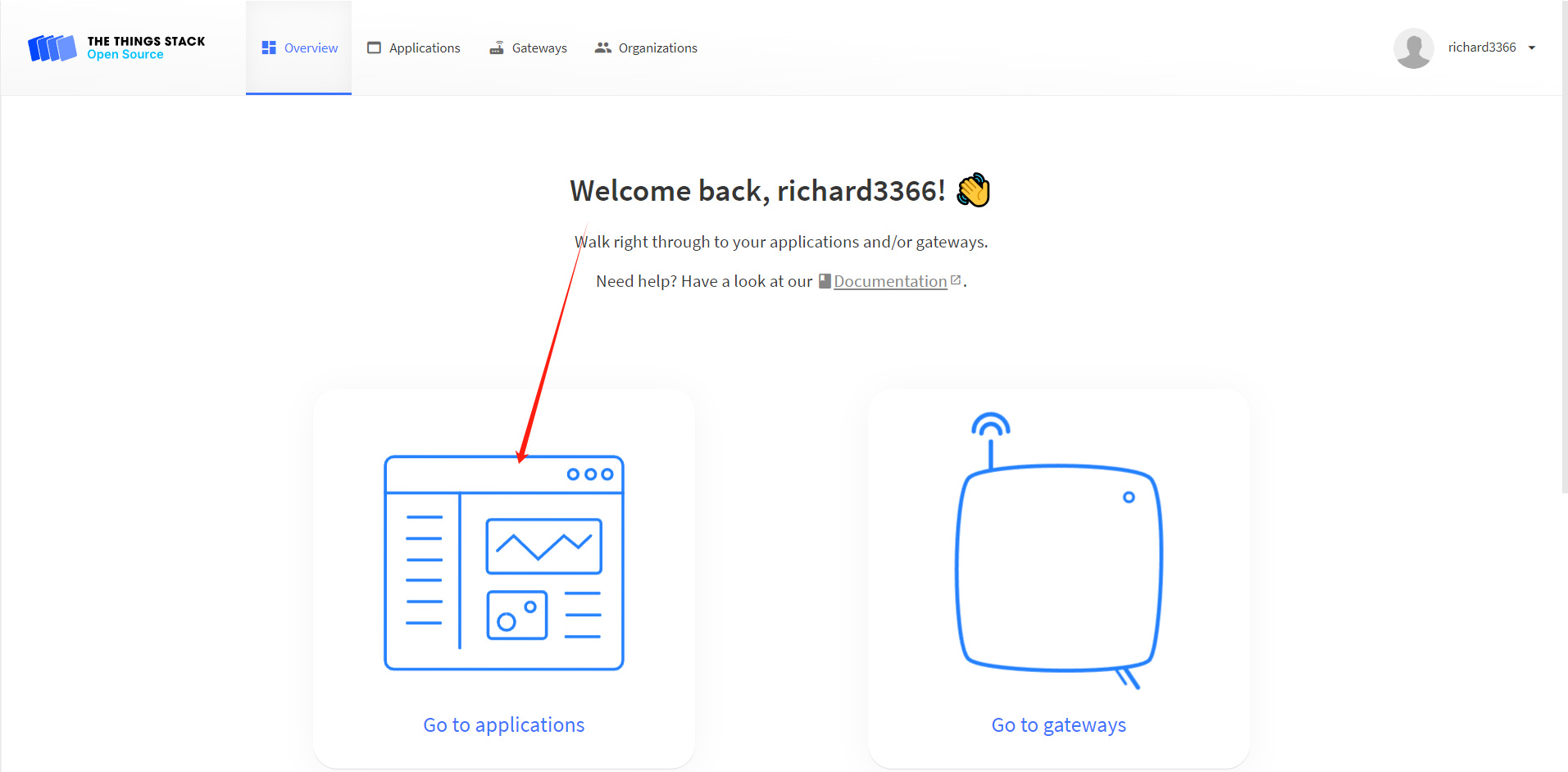
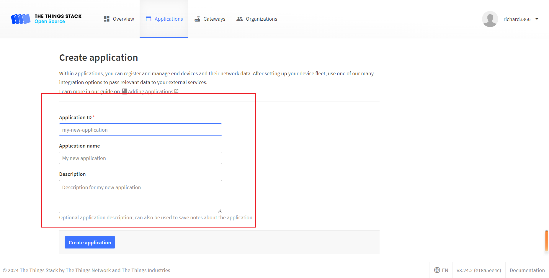
- Create application
- You can freely fill in the Application information in the red box, and click
Creat applicationwhen you're done.
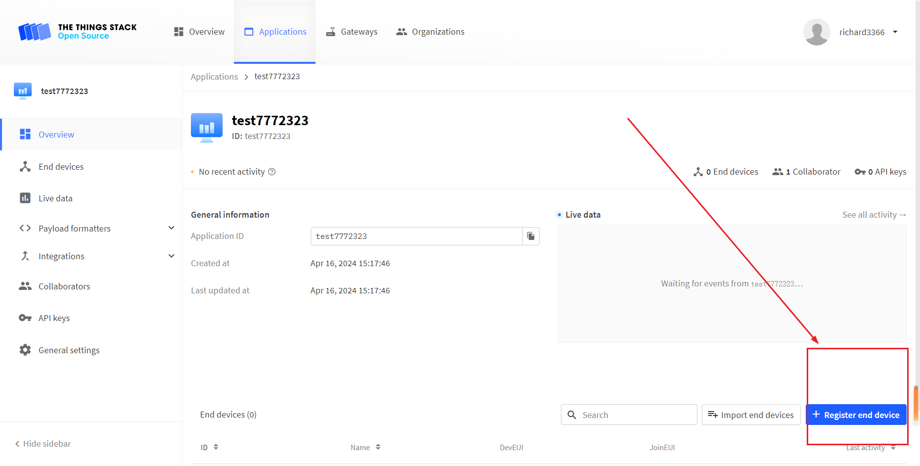
- Register an end device.
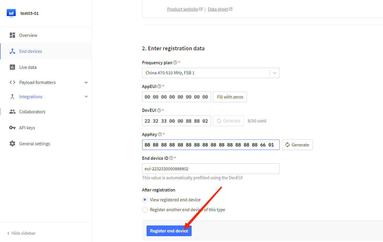
- Choose
Enter end device specifics manually, Select the frequency band corresponding to the node,
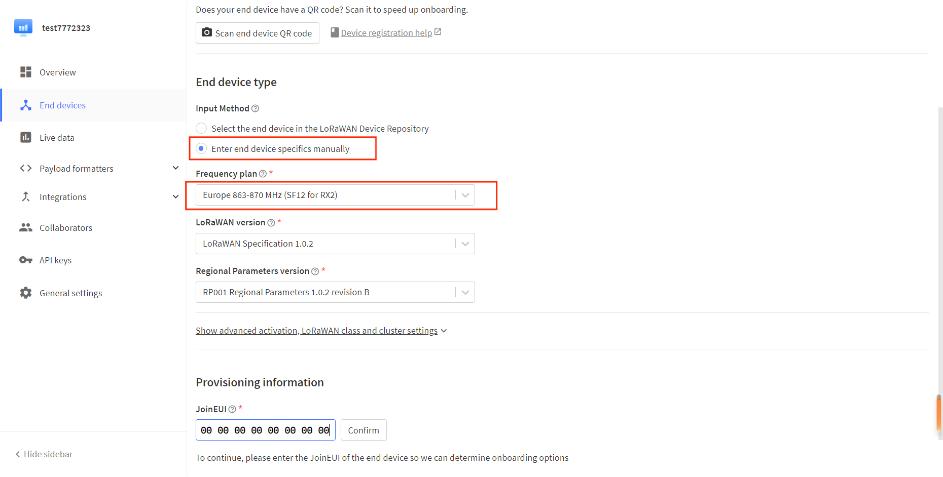
- The LoRaWAN version is chosen to be 1.0.2 B
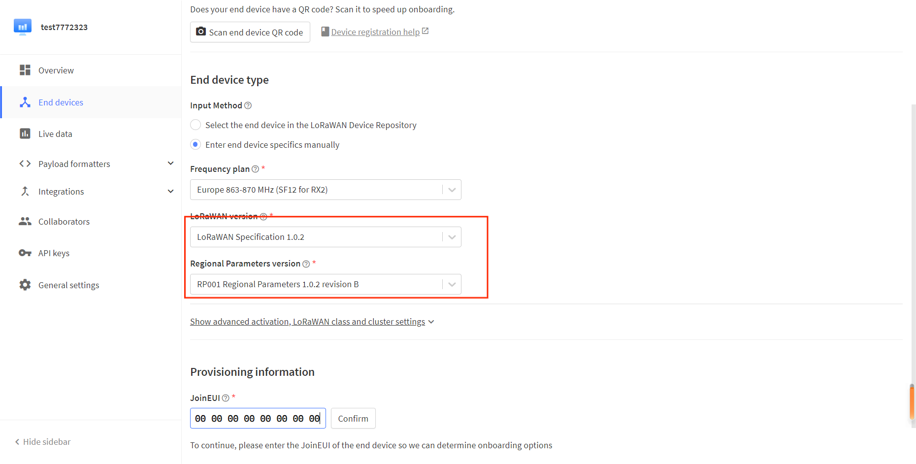
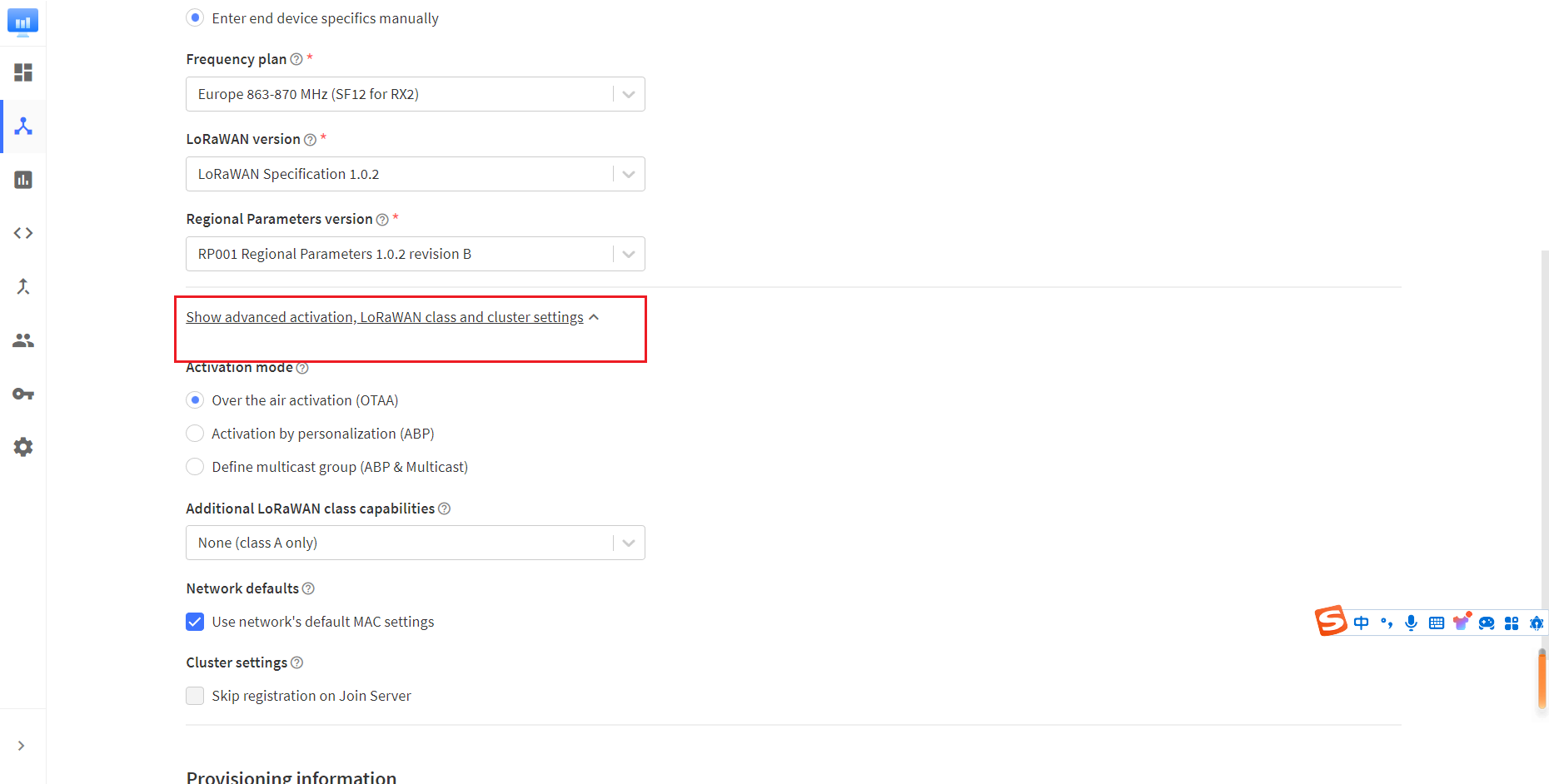
The Show advanced activation, LoRaWAN class and cluster settings option has some other LoRaWAN parameter Settings such as OTAA/ABP.CLASS A/C, these parameters default to OTAA and CLASS A, in general need to be consistent with the node Settings.
- Fill in JoinEUI and click confirm.
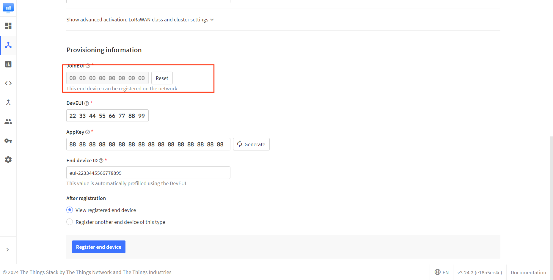
In code or some application products, JoinEUI is represented as AppEUI.
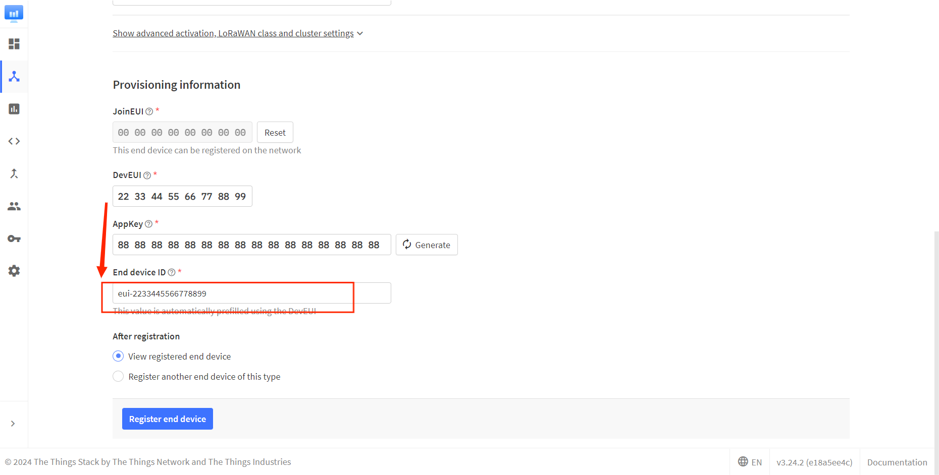
- Fill in DevEUI and AppKey.
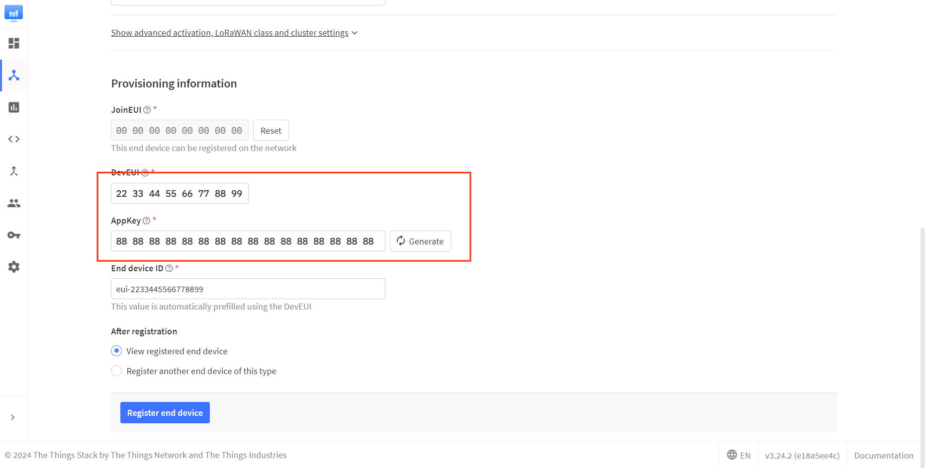
The End device ID is automatically generated when you fill in DevEUI.
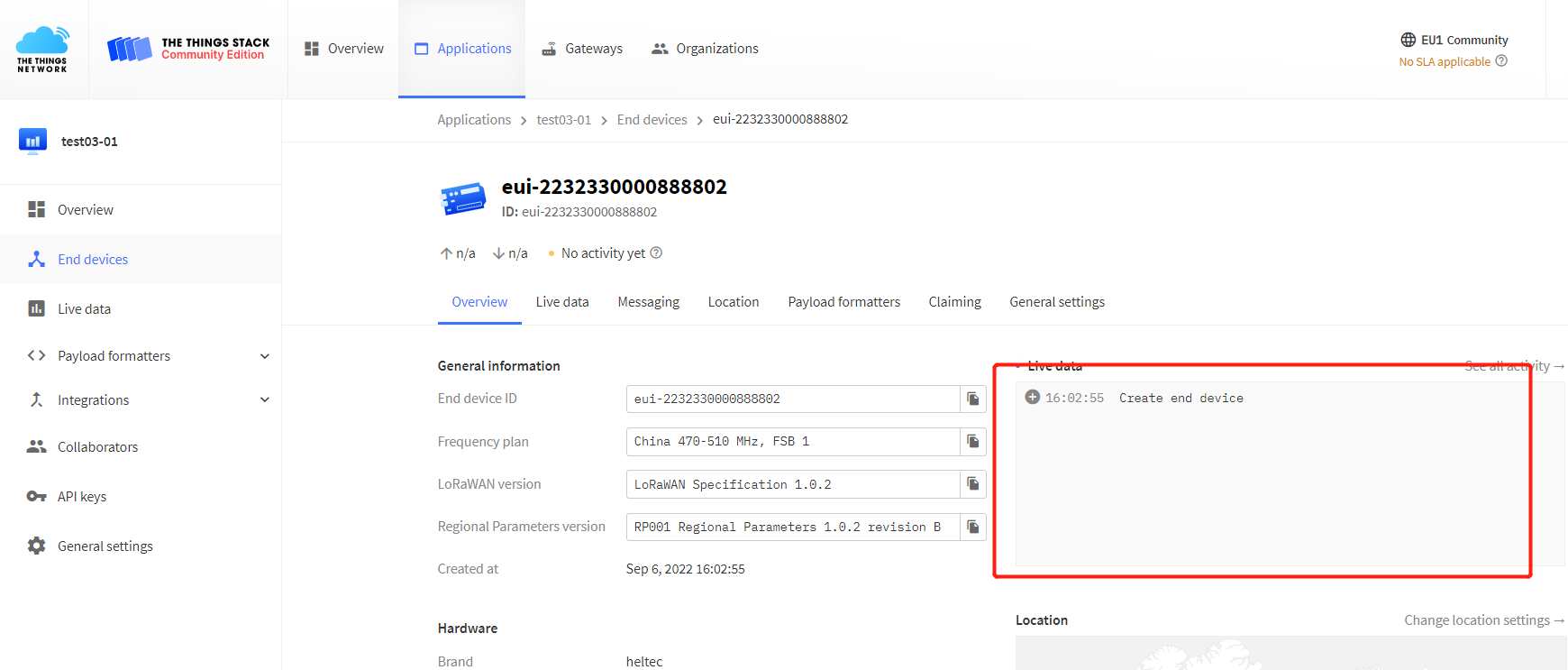
- Click to register.
After registration is complete, if all is well, you will see the device active.
ChirpStack is not Heltec's business, we cannot provide technical support for this platform, please refer to the official documentation of ChirpStack.
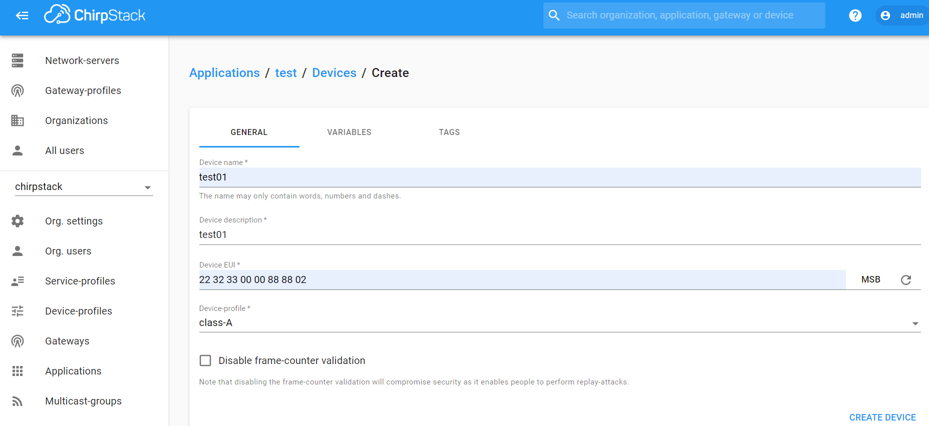
Register a new device in ChirpStack’s “Applications” page. Enter the device name, description, DevEUI. Select Device-profile.
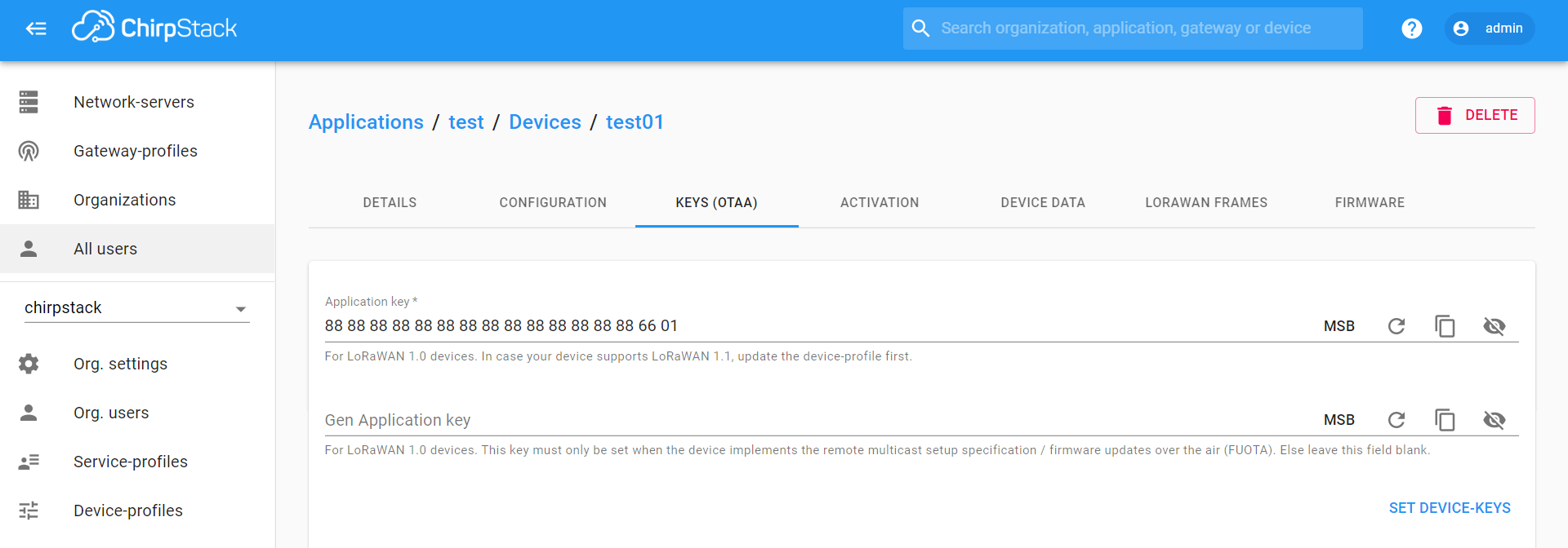
Enter the Application key of the device.
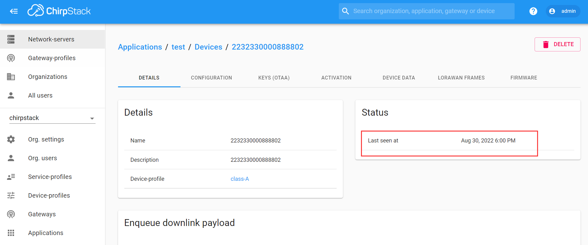
After registration is complete, if all is well, you will see the device active.
Important Hints
Please double check the following two things:
- The LoRaWAN parameters is the same as server!
- The listening frequency of your LoRa Gateway is the same as ESP32 LoRa node's sending frequency. We strictly follow LoRaWAN™ 1.0.2 Regional Parameters rB;
Meshtastic® is a project that enables you to use inexpensive LoRa radios as a long range off-grid communication platform in areas without existing or reliable communications infrastructure. This project is 100% community driven and open source! For a more detailed description of Meshtastic please refer to their website and forum: https://meshtastic.org.
How to Install ESP32 Series Meshtastic Firmware
Using the four flashing methods for the WiFi LoRa 32 V4 as an example, the installation process is largely the same for other ESP32 series devices.
Supported ESP32 Devices for Meshtastic Web Flasher
| Product | Description |
|---|---|
| WiFi LoRa 32 V3 | ESP32-S3 · SX1262 · LoRa / Wi-Fi / BLE · OLED |
| WiFi LoRa 32 V4 | 28 dBm TX Power |
| WiFi LoRa 32 Expansion Kit (Glass Panel) | A complete expansion kit for the WiFi LoRa 32 series |
| Wireless Tracker | it comes with a GPS module. |
| Wireless Stick Lite | no screen |
| Wireless Paper | It comes with E-Ink screen |
| Vision Master E213 | 2.13 inch E-Ink Display |
| Vision Master E290 | 2.90 inch E-Ink Display |
| Vision Master T190 | 1.90 inch TFT Display |
How to Use Meshtastic
This topic uses the WiFi LoRa 32 V3 as an example to demonstrate the complete Meshtastic setup, starting from flashing the firmware.
Install ESP32 USB to Serial Drivers
Use a USB cable to connect your computer to your device. Open your Device Manager, Port, if your computer doesn't recognize the device, You may need to install a driver from Silicon Labs for the CP210X USB to UART bridge: CP210X USB to UART bridge - Download
After installing the driver, make sure to reboot your computer to finish the installation process.
Flash Meshtastic Firmware via the Web Flasher
The Web-Based Installer requires either Chrome or Edge browsers but is an excellent choice for quickly flashing devices. This method is highly recommended for firmware flashing, especially for new users of the project, as it is easy to use.
-
Plug in your device.
-
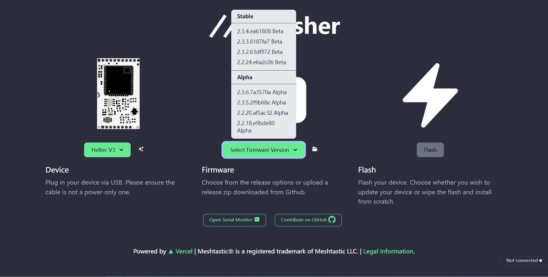
Visit flasher.meshtastic.org requires Chrome or Edge browser. Follow the instructions, select the model of the corresponding board.
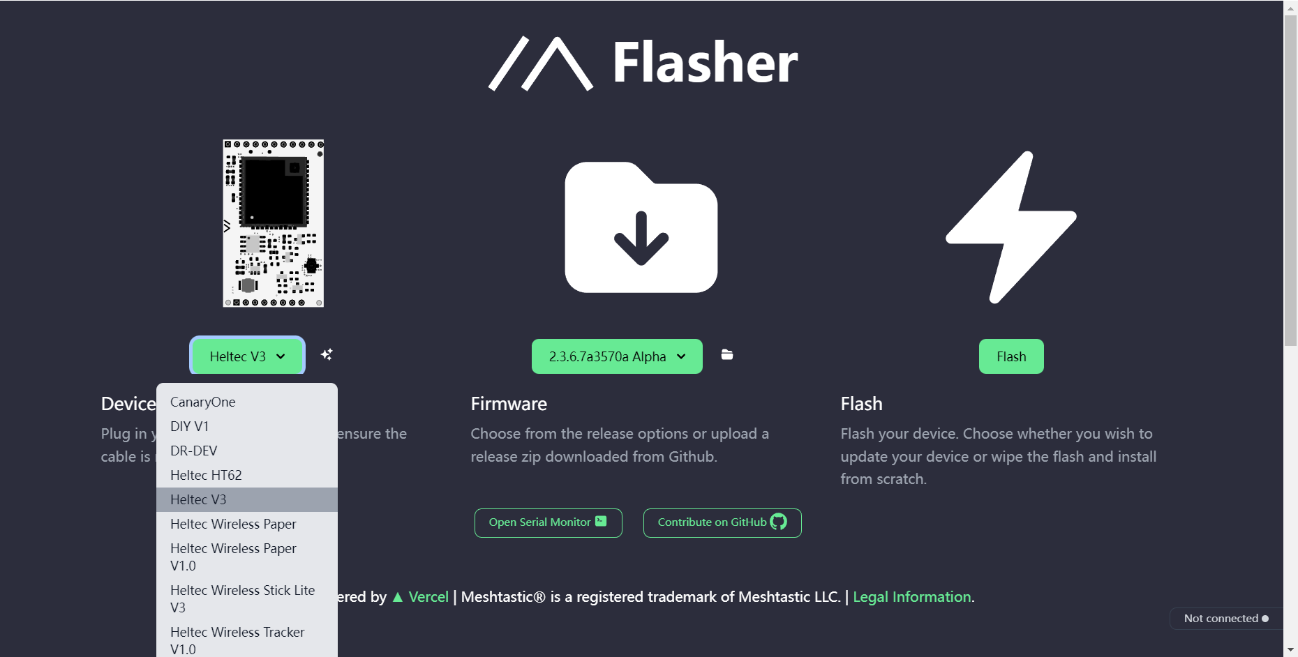
- Select the appropriate firmware version; the latest stable version is generally recommended.
- Click button to flash.
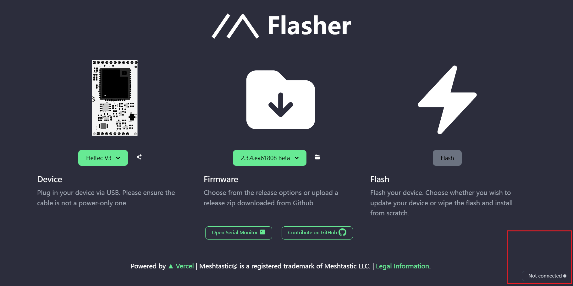
Network issues can cause Flash buttons to fail to click. Of course, sometimes it appears gray, but it can still be manipulated.
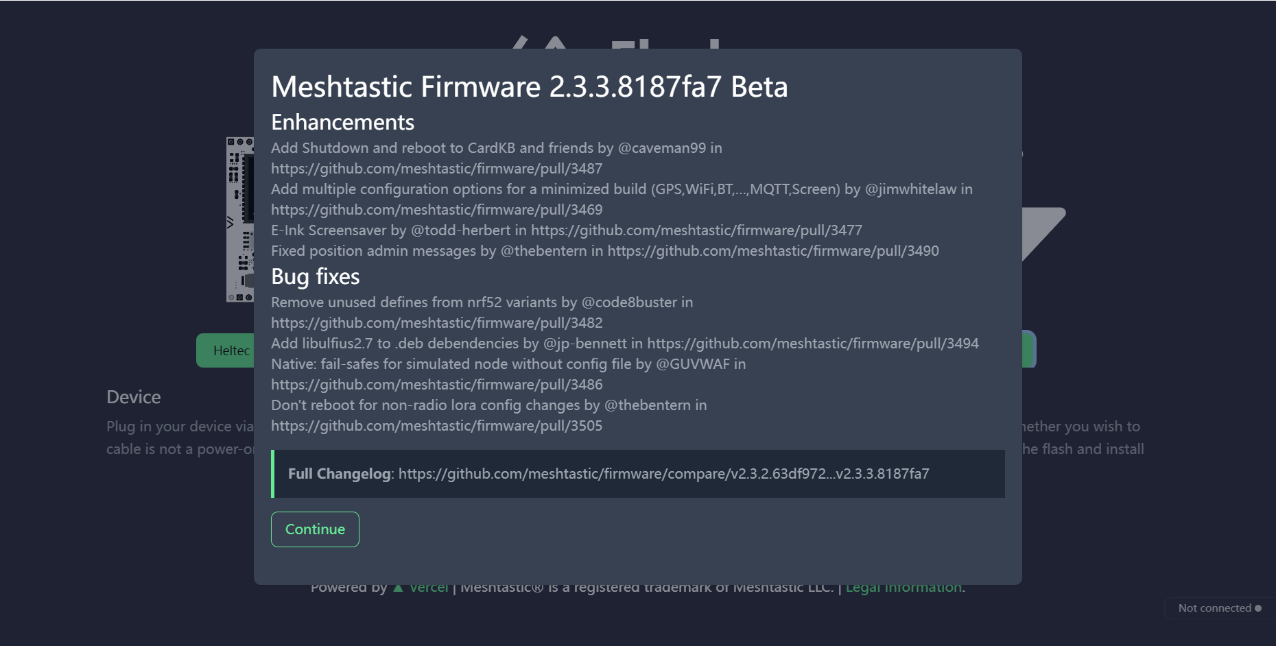
- Continue.
- Click the
Full Erase and Install, thenErase flash and install.
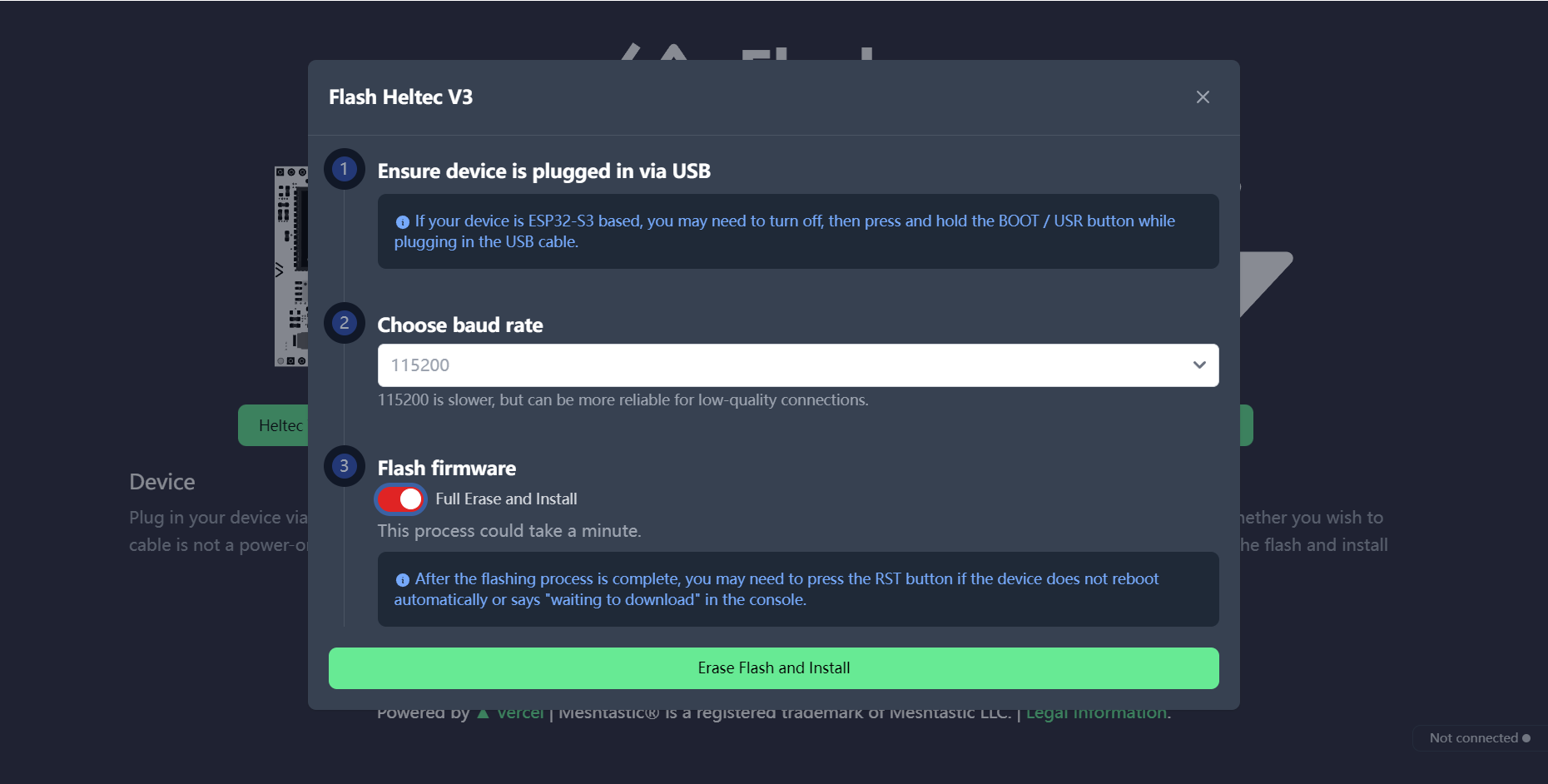
Network problems cause Flash pages to stay in "Conneting......".
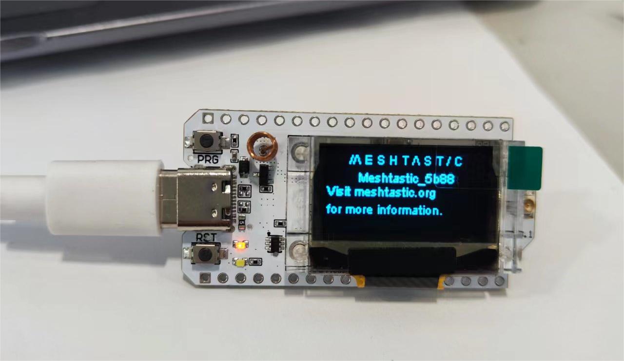
- Wait for the firmware to flash, and your device screen will display Meshtastic.
Install the Meshtastic App
Let's take Android as an example to show you how to use the APP at an entry-level. We will continue to update IOS Web operations in the future.
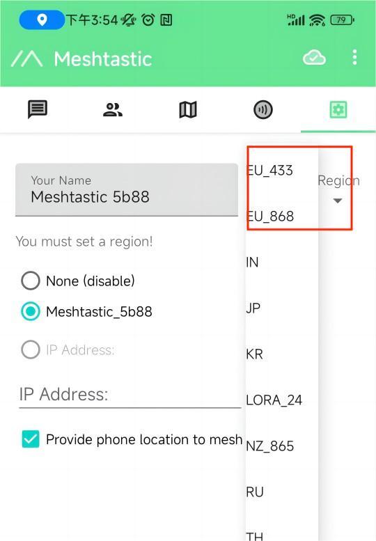
Set Regional Settings
In order to start communicating over the mesh, you must set your region. This setting controls which frequency range your device uses and should be set according to your regional location.
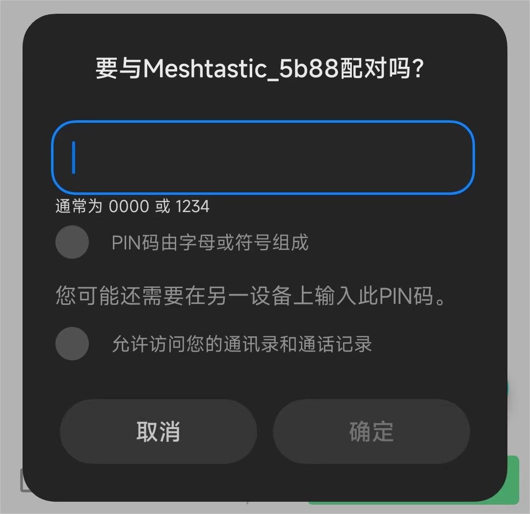
- Open the app, find your device via Bluetooth as shown below. Click to connect the device.
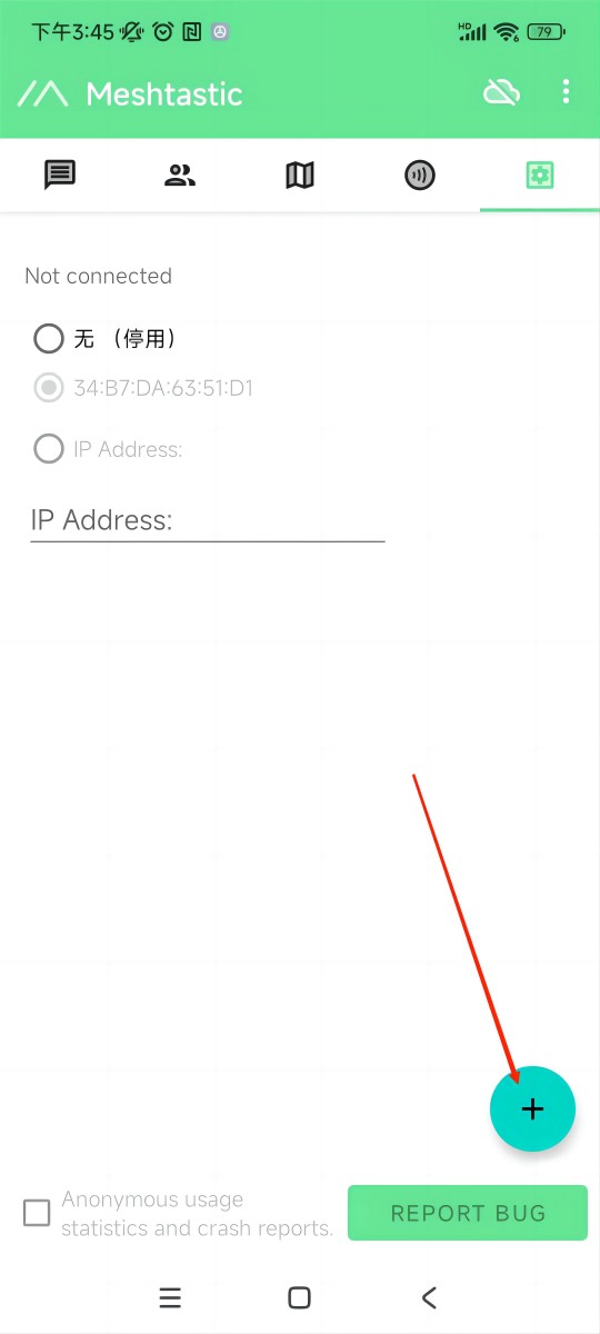
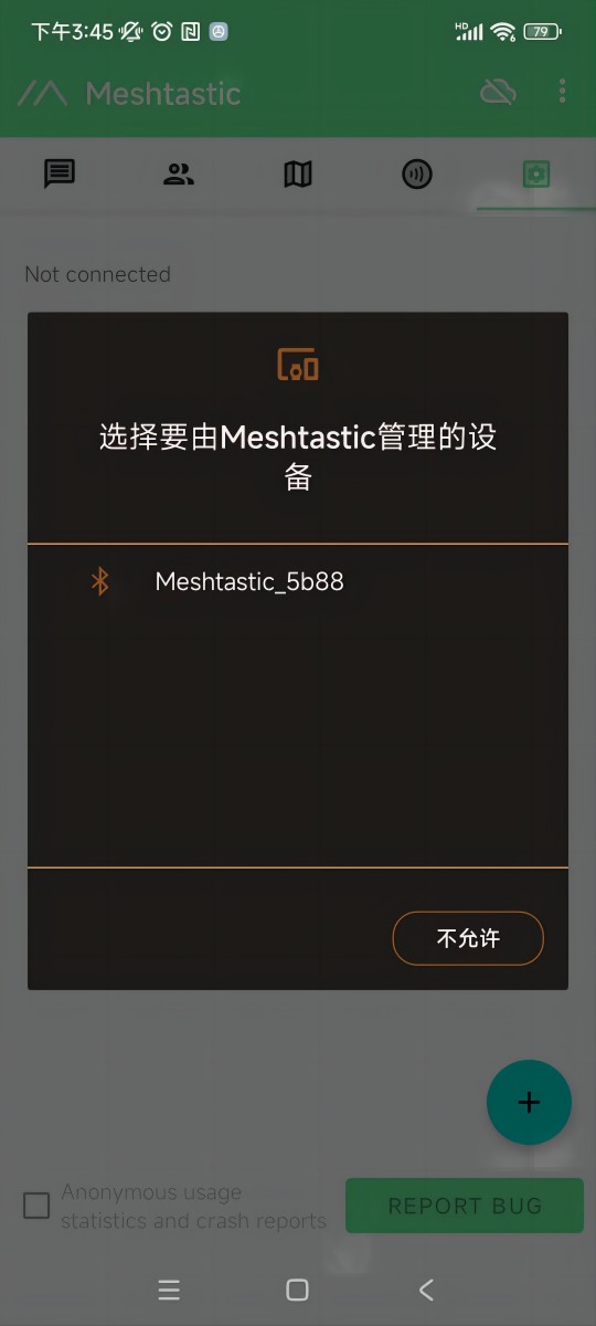
If a window asks for a CAPTCHA appears, you need to look at your device's screen. The default CAPTCHA for devices without a screen is usually 123456. If not, contact the firmware issuer.
- Once paired, Click "UNSET" next to the device name. Select the region from the list according to your regional location. Of course, your hardware must support this frequency band.
You can refer to this link for the relationship between LoRaWAN bands and regions:LoRaWAN_frequency_plans_by_country
EU_433 and EU_868 have to adhere to an hourly duty cycle limitation of 10%. Your device will stop transmitting if you reach it, until it is allowed again
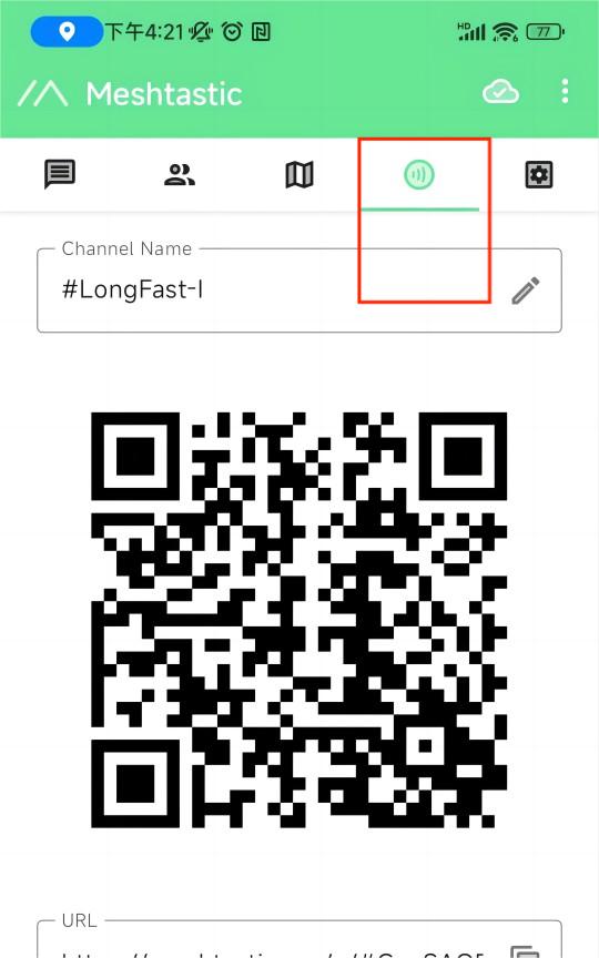
- Click the option below to select the channel you want to join.
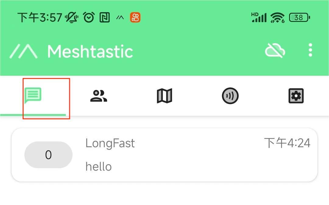
Get Started With Meshtastic
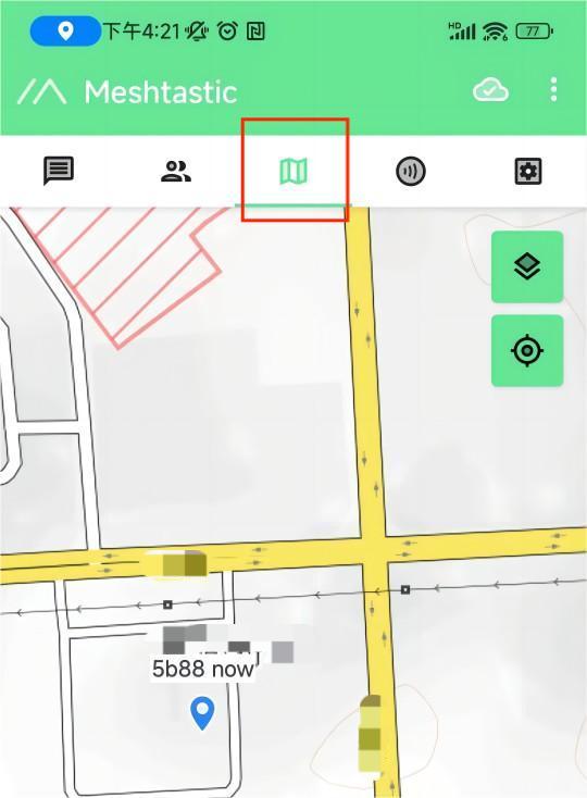
- The map option will be able to view the location information of the companion, which can be provided by the GPS module on the device, or by the phone to which the device is connected.
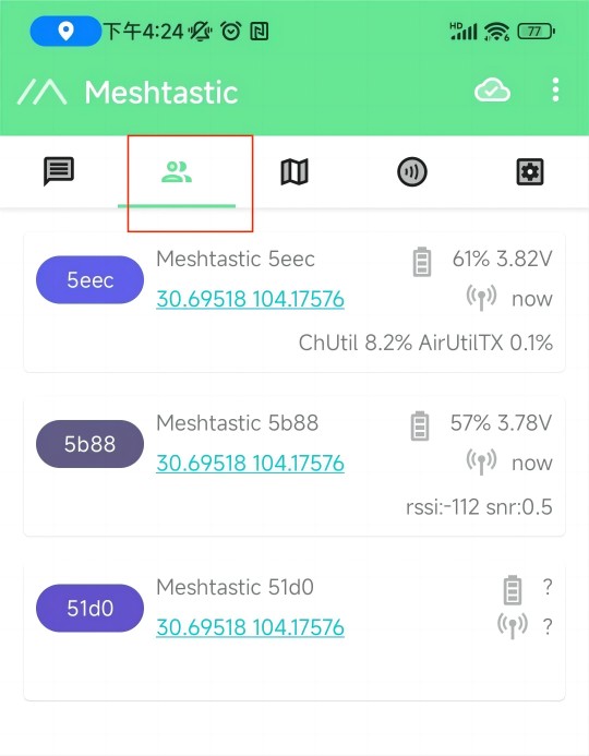
- The options below show some information about the companion device, such as latitude and longitude, signal strength, battery level, and so on.
- This is where you'll see the messages you want to send and receive, and they'll be displayed on the device screen.
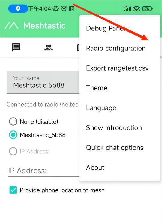
More Settings and Usage
Click the top right button to see more configurable options.
Meshtatic devices
| Test Sample | Peak Temperature on Backside |
|---|---|
| Without Heat Sink | 63.6°C |
| With dual Heat Sinks | 53.5°C (🔻10°C) |