PlatformIO Guide
This guide uses the WiFi LoRa 32 V4 development board as a reference example.
PlatformIO is an embedded development environment built on Visual Studio Code. Before using PlatformIO, ensure that Visual Studio Code is installed on your system.
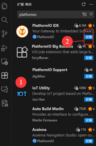
1.Install the PlatformIO IDE
Open the Extensions view by pressing Ctrl + Shift + X. In the search bar, enter PlatformIO IDE and install the PlatformIO IDE extension.
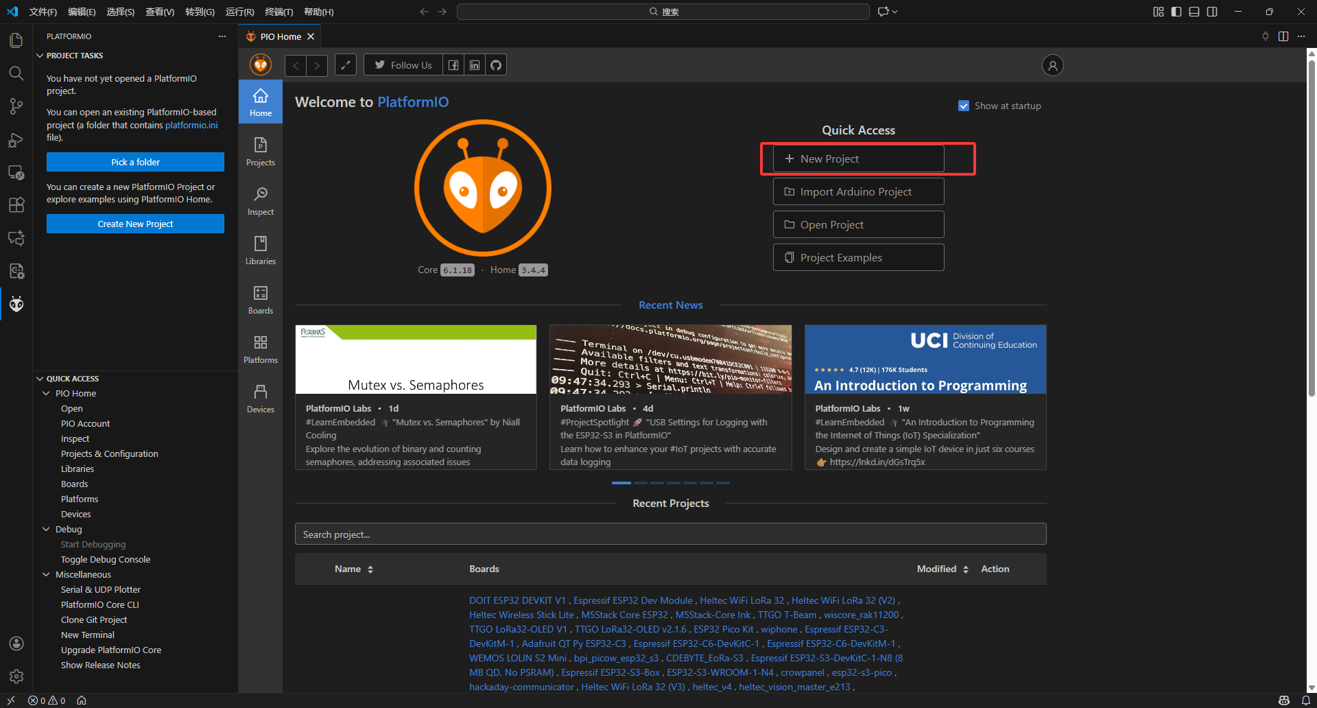
2.Create Project
Press Ctrl + Shift + P to open the Command Palette, enter PlatformIO Home, and press Enter to launch the PlatformIO extension.
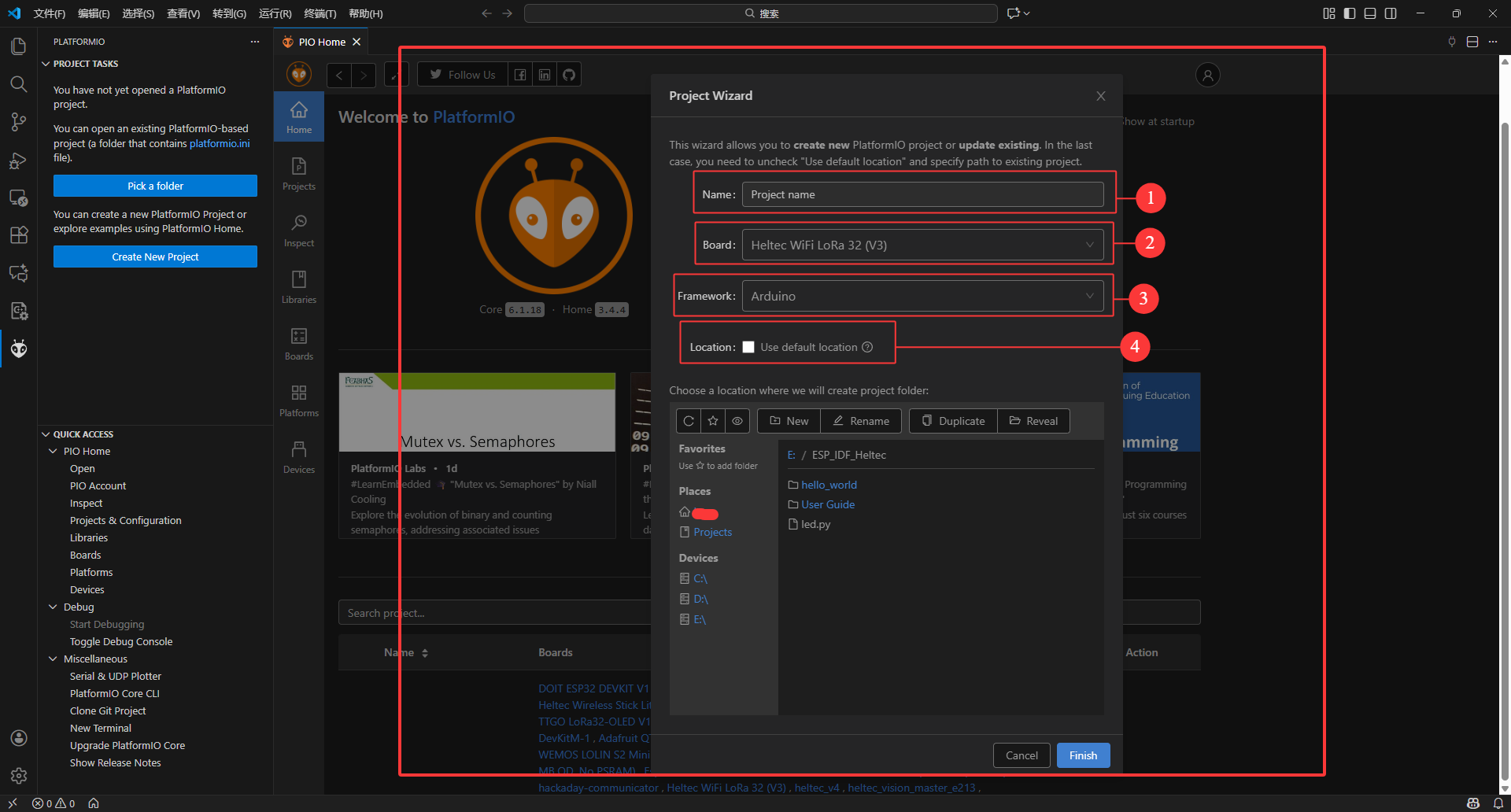
- Name: Customize project name
- Board: Select Heltec WiFi LoRa 32 (V3), as the V4-related submissions are still pending approval
- Framework: Select Arduino
- Location: Select project location
3.Routine usage
Since the project was created for the V3 board, some modifications are required to better adapt it for the V4 board.
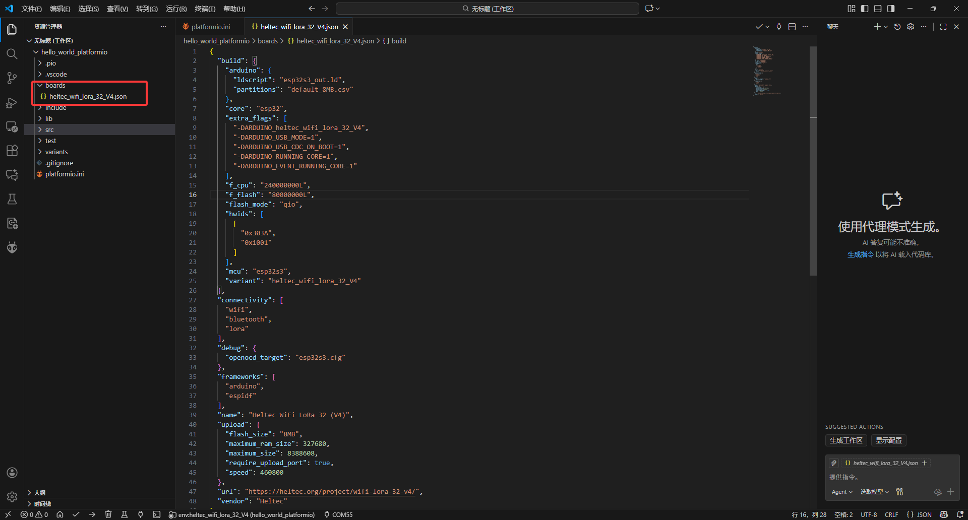
1.Create a Board Definition File: Within the project directory, create a folder named boards. Then, create a new file named heltec_wifi_lora_32_V4.json in this folder and add the following code to define the board.
heltec_wifi_lora_32_V4.json:
{
  "build": {
    "arduino": {
      "ldscript": "esp32s3_out.ld",
      "partitions": "default_8MB.csv"
    },
    "core": "esp32",
    "extra_flags": [
      "-DARDUINO_heltec_wifi_lora_32_V4",
      "-DARDUINO_USB_MODE=1",
      "-DARDUINO_USB_CDC_ON_BOOT=1",
      "-DARDUINO_RUNNING_CORE=1",
      "-DARDUINO_EVENT_RUNNING_CORE=1"
    ],
    "f_cpu": "240000000L",
    "f_flash": "80000000L",
    "flash_mode": "qio",
    "hwids": [
      [
        "0x303A",
        "0x1001"
      ]
    ],
    "mcu": "esp32s3",
    "variant": "heltec_wifi_lora_32_V4"
  },
  "connectivity": [
    "wifi",
    "bluetooth",
    "lora"
  ],
  "debug": {
    "openocd_target": "esp32s3.cfg"
  },
  "frameworks": [
    "arduino",
    "espidf"
  ],
  "name": "Heltec WiFi LoRa 32 (V4)",
  "upload": {
    "flash_size": "8MB",
    "maximum_ram_size": 327680,
    "maximum_size": 8388608,
    "require_upload_port": true,
    "speed": 460800
  },
  "url": "https://heltec.org/project/wifi-lora-32-v4/",
  "vendor": "Heltec"
}
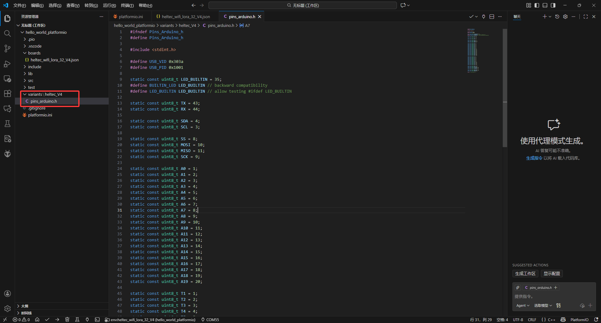
2.Pin Configuration: Within the project's root directory, create a folder named variants.
Then, create a subfolder named heltec_V4 inside variants, and add a new file called pins_arduino.h in this subfolder.
pins_arduino.h:
#ifndef Pins_Arduino_h
#define Pins_Arduino_h

#include <stdint.h>

#define USB_VID 0x303a
#define USB_PID 0x1001

static const uint8_t LED_BUILTIN = 35;
#define BUILTIN_LED LED_BUILTIN // backward compatibility
#define LED_BUILTIN LED_BUILTIN // allow testing #ifdef LED_BUILTIN

static const uint8_t TX = 43;
static const uint8_t RX = 44;

static const uint8_t SDA = 4;
static const uint8_t SCL = 3;

static const uint8_t SS = 8;
static const uint8_t MOSI = 10;
static const uint8_t MISO = 11;
static const uint8_t SCK = 9;

static const uint8_t A0 = 1;
static const uint8_t A1 = 2;
static const uint8_t A2 = 3;
static const uint8_t A3 = 4;
static const uint8_t A4 = 5;
static const uint8_t A5 = 6;
static const uint8_t A6 = 7;
static const uint8_t A7 = 8;
static const uint8_t A8 = 9;
static const uint8_t A9 = 10;
static const uint8_t A10 = 11;
static const uint8_t A11 = 12;
static const uint8_t A12 = 13;
static const uint8_t A13 = 14;
static const uint8_t A14 = 15;
static const uint8_t A15 = 16;
static const uint8_t A16 = 17;
static const uint8_t A17 = 18;
static const uint8_t A18 = 19;
static const uint8_t A19 = 20;

static const uint8_t T1 = 1;
static const uint8_t T2 = 2;
static const uint8_t T3 = 3;
static const uint8_t T4 = 4;
static const uint8_t T5 = 5;
static const uint8_t T6 = 6;
static const uint8_t T7 = 7;
static const uint8_t T8 = 8;
static const uint8_t T9 = 9;
static const uint8_t T10 = 10;
static const uint8_t T11 = 11;
static const uint8_t T12 = 12;
static const uint8_t T13 = 13;
static const uint8_t T14 = 14;

static const uint8_t Vext = 36;
static const uint8_t LED = 35;
static const uint8_t RST_OLED = 21;
static const uint8_t SCL_OLED = 18;
static const uint8_t SDA_OLED = 17;

static const uint8_t RST_LoRa = 12;
static const uint8_t BUSY_LoRa = 13;
static const uint8_t DIO0 = 14;

#endif /* Pins_Arduino_h */
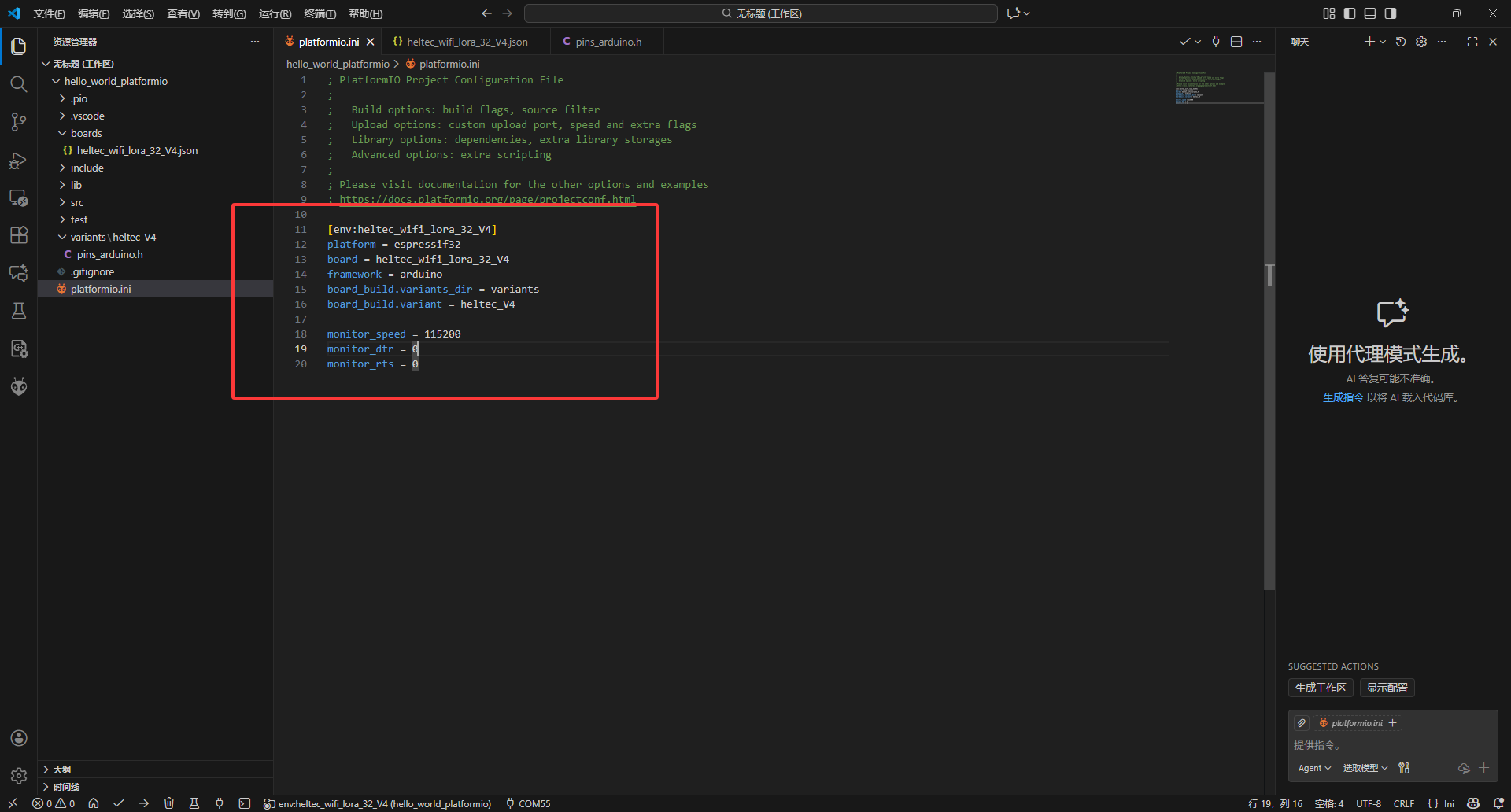
3.Modify the platformio.ini file in your project directory to update the configuration for the Heltec V4 board.
platformio.ini:
[env:heltec_wifi_lora_32_V4]
platform = espressif32
board = heltec_wifi_lora_32_V4
framework = arduino
board_build.variants_dir = variants
board_build.variant = heltec_V4

monitor_speed = 115200
monitor_dtr = 0
monitor_rts = 0
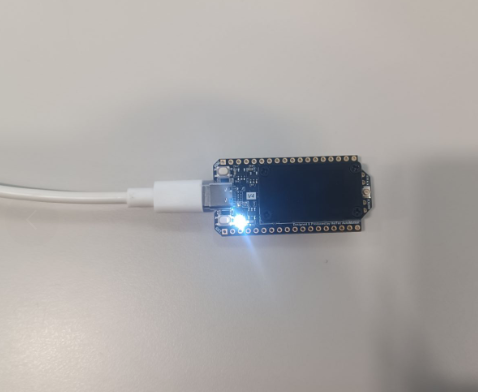
4.Example Code: Open the src\main.cpp file and write your program. The following is a simple example, when the BOOT button is pressed, the LED will turn on, and "Hello World!!!" will be printed to the serial monitor.
main.cpp:
#include <Arduino.h>

#define Boot_Key 0
#define Led      35
void setup() {
  // put your setup code here, to run once:
  Serial.begin(115200);
  pinMode(Boot_Key, INPUT_PULLUP);
  pinMode(Led, OUTPUT);
}

void loop() {
  // put your main code here, to run repeatedly:
  if(digitalRead(Boot_Key)==0) {
    digitalWrite(Led,HIGH);
    Serial.print("hello world !!! \n");
    delay(1000);
    digitalWrite(Led,LOW);
  }
  delay(100);
}
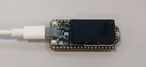
5.Connect the development board to your computer and identify the correct serial port.
6.Select the V4 board environment, ensure the correct serial port is selected, and then upload the code to the board.
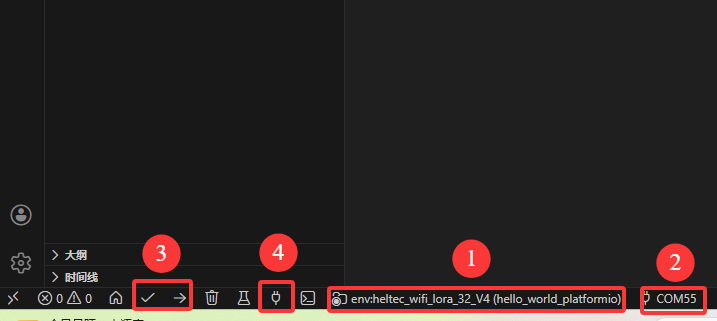
- 1: Select development board environment-v4
- 2: Select device port
- 3: Code compilation and upload
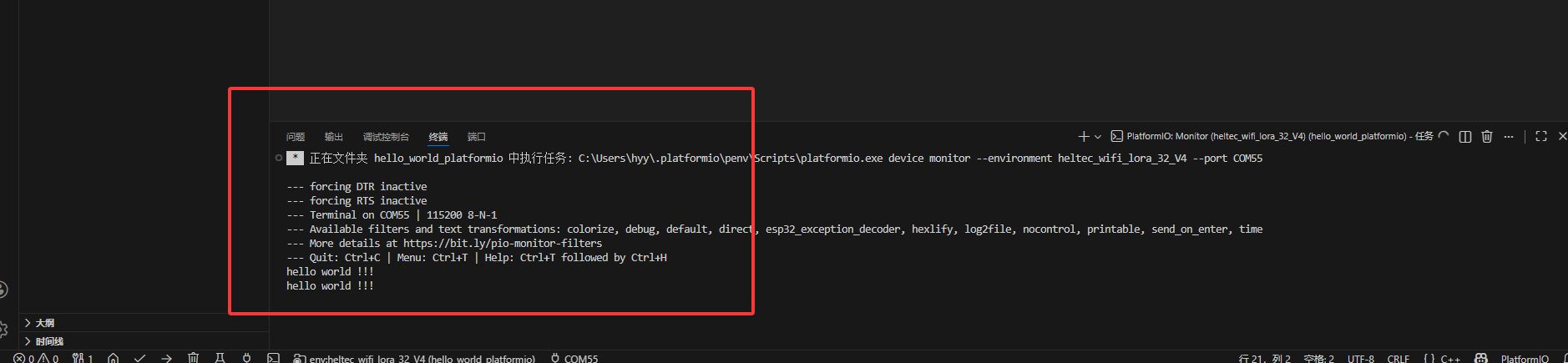
- 4: Open the serial port
7.Press the BOOT button to observe the following output in the serial monitor.
Refer to the official documentation for additional information on PlatformIO usage.